Power connection, Main disconnect – Daktronics AF-3165-34-RGB User Manual
Page 21
Electrical Installation
17
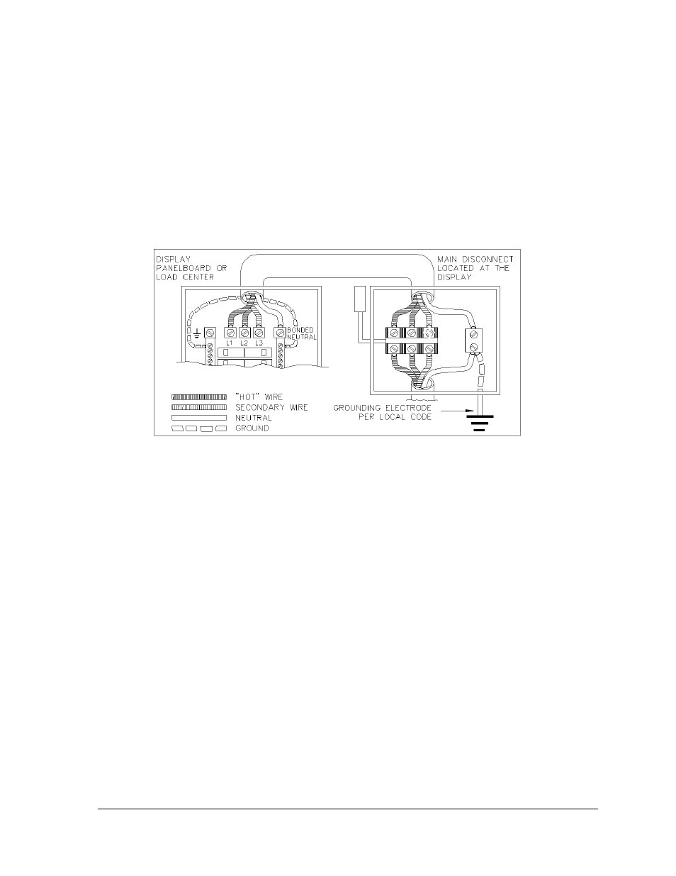
Installation with Only a Neutral Conductor Provided
Installations where no grounding conductor is provided must comply with article 250-32 of the
National Electrical Code. If the installation in question meets all of the requirements of article 250-32,
the following guidelines must be observed:
Connect the grounding electrode cable at the local disconnect, never at the sign panel board.
A disconnect that opens all of the ungrounded phase conductors should be used.
The neutral and the ground conductors should be bonded in the sign panel board.
Refer to Figure 18 below for installation details.
Power Connection
Incoming power is connected within the power termination enclosure. Complete the following steps to
terminate the hot and neutral wires at the termination block within the enclosure. Refer to Drawing A-
154965 and the appropriate schematic for your display size.
1. Access the enclosure by removing the left bottom two modules as described in Section 3.5.
2. Route the power cables through the power conduit in the rear of the sign and to the enclosure.
3. Connect the white neutral wire to neutral bus.
4. If one power line is being terminated (120VAC), connect the black “hot” wire to L1. Install
jumper per Note 1 on Drawing A-154965.
5. If two power lines are being terminated (120/240VAC). Connect the second “hot” wire to L2.
6. Connect the green grounding wire to the grounding bus L1. Refer to Figure 20 above.
Main Disconnect
The National Electrical Code requires the use of a lockable power disconnect near the display. Provide
a lockable disconnect switch (knife switch) at the display location so that all power lines can be
completely disconnected. Use a 3-conductor disconnect so that both hot lines and the neutral can all be
disconnected. The main disconnect should be mounted at or near the point of power supply connection
to the display. A main disconnect is to be provided for each supply circuit to the display.
The disconnecting means must be located in a direct line of sight from the display or outline lighting
that it controls. This requirement provides protection by enabling a worker to keep the disconnecting
means within view while working on the display.
Exception: Disconnecting means that are capable of being locked in the open position may be located
elsewhere.
Figure 18: Installation with only Neutral Conductor Provided