Modem, Figure 25: modem/ layout – Daktronics AF-3165-34-RGB User Manual
Page 26
Electrical Installation
22
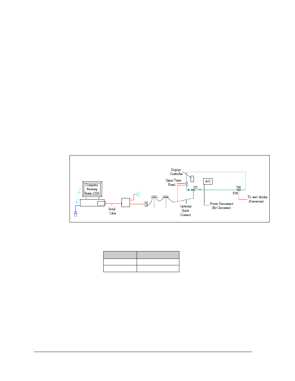
Modem
A display that is controlled using a modem requires the use of an internal or external modem at the
computer. The local phone company must provide a dedicated phone line to the display and identify
the colors used for “Tip” and “Ring”. The telephone cable is run to the Signal termination Panel in the
display or to a plug that is connected to the Quick Connect at the display. The phone cable must be
routed though conduit. Do not run signal and display power through the same conduit. Refer to
Drawing A-174342 for system layout.
1. If using a quick connect cable, connect the phone line to J32 on the back of the display.
2. When connecting directly to the display, terminate the phone line to TB5 on the Signal
Termination Panel. If the phone company provided a phone termination box in the display a
straight phone cable can be connected from the box to the J1 Phone IN on the modem board
in the display. Drawing
B-175387 shows the terminal block wiring.
3. A 6-conductor phone cord with RJ11 connectors (Daktronics part number 0A-1137-0160)
relays the signal to the modem. A second phone cord (Daktronics part number 0A-1137-0160)
transfers data from J2 on the modem to J1 (RS232 IN) on the controller.
Note: The jumper on the controller board must be closed to recognize that a modem is being
used with the display.
Phone Line to Phone Termination Block (A35)
Field Cabling Phone Line (TB5)
Red
Pin 1 (Tip)
Green
Pin 2 Ring)
Figure 25: Modem/ Layout