Fiber interconnection, Can interconnection – Daktronics AF-3165-34-RGB User Manual
Page 32
Electrical Installation
28
Fiber Interconnection
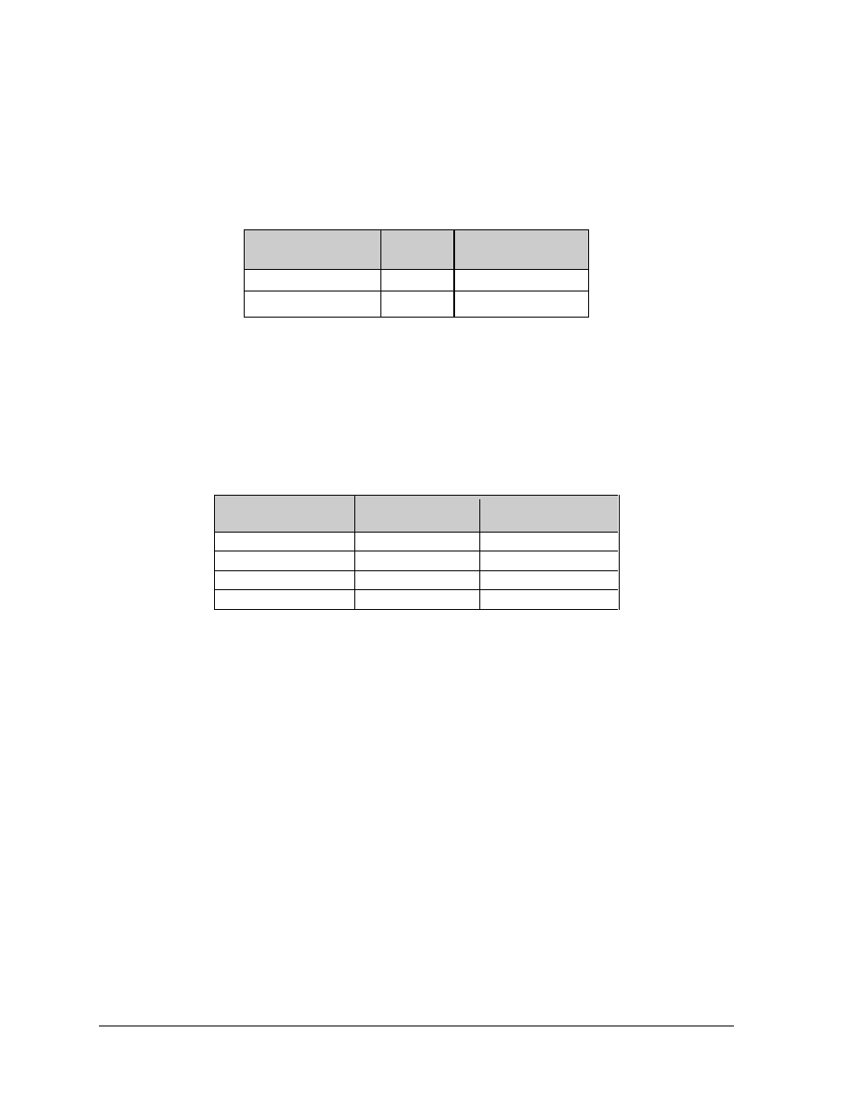
A four-conductor fiber cable is used in connecting two or more displays in the Fiber Interconnection
method. Connect the fiber cable to the fiber cards of the display as described in Drawing A-174344
and on the following table.
Face A Data Out
(A34)
Field
Cabling
Face B Data In
(A34)
J2 (TX1)
J5 (RX2)
J3 (RX1)
J4 (TX2)
CAN Interconnection
If the display is using the Quick Connect interconnect cable, this connection is already complete. Make
sure the terminating resistor is mounted to the display at the Temp sensor quick connect location.
If the interconnect cable was not used a 4-conductor shielded cable is used to the temp sensor for side
one to side two. One end terminates at the “CAN US/DS” 8-position terminal block (A35-TB4) on the
first display. The other end terminates
at
the “CAN US/DS” 8-position terminal block (A35-TB4) in
the second display.
Face A CAN DS
(A35-TB4)
Field Cabling
Face B CAN US
(A35-TB4)
Pin 6 (CAN H)
Green
Pin 2 (CAN H)
Pin 7 (CAN L)
White
Pin 3 (CAN L)
Pin 8 (GND CAN)
Black
Pin 4 (GND CAN)
Shield
Pin 5 (Shield)
Note: Cable shield should not be terminated in Face A.
3.9 Optional Temperature Sensor Electrical Installation
Reference Drawing:
Schematic, Signal Wiring, Internal .............................. Drawing B-175387
After mounting the optional temp sensor as described in Section 2.6 follow these steps to complete the
electrical installation.
Using the Quick Connect and 10 foot cable
1. Run ¾" conduit from the sensor location to the Quick connect Temp Sensor input at the back
of the first display. The cable must be routed through ¾" metal conduit that should be earth-
grounded to protect the sensor and controller from lightning damage.
2. Route the cable through the conduit and connect the Quick Connect to the Temp Sensor input
on the back of the first display.