Signal termination between two (or more) signs, Rs422 interconnection, Figure 31: signal termination panels – Daktronics AF-3165-34-RGB User Manual
Page 31: 8 signal termination between two (or more) signs
Electrical Installation
27
3.8 Signal Termination Between Two (or More) Signs
Reference Drawings:
System Riser Diagram, Modem ................................. Drawing A-174342
System Riser Diagram, RS422 .................................. Drawing A-174135
System Riser Diagram, RS232 .................................. Drawing A-174341
System Riser Diagram Fiber ...................................... Drawing A-174344
Signal Input, Venus 1500 ........................................... Drawing A-175387
System Riser, QC Outdoor Radio, V1500 .................. Drawing A-177006
RS-422 Interconnection
The Quick Connect cable is the most common method of terminating signal between two displays. The
four-foot cable goes from the RS-422 OUT on the first display to the RS-422 IN on the second display.
If the displays are not back-to-back, or are too far apart for the Quick connect interconnect cable to
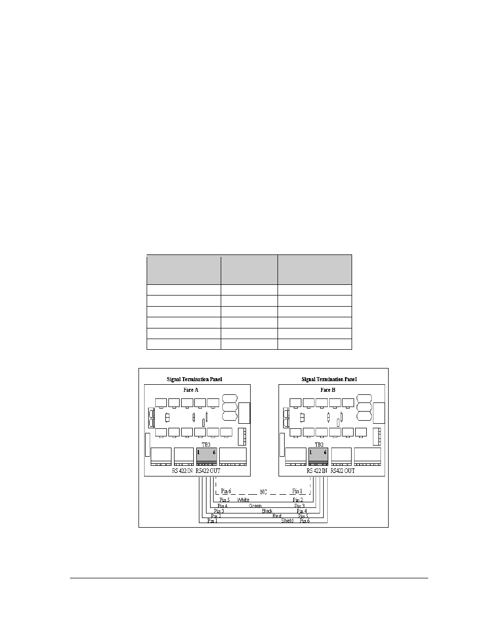
reach, a 4-conductor shielded cable of the correct length is used. One end will connect at the “RS422
OUT” 6-position terminal block (A35-TB3) in the Signal Termination Panel of the first display, and
the other end of the cable will terminate on the “RS422 IN” 6-position terminal block (A35-TB2) on
the Signal Termination Panel of the second display.
Face A – RS422
OUT
(A35-TB3)
Field Cabling
Face B – RS422 IN
(A35-TB2)
Pin 1 (GND)
Shield
Pin 6 (GND)
Pin 2 (D2OUT-N)
Red
Pin 5 (D1IN-N)
Pin 3 (D2OUT-P)
Black
Pin 4 (D1IN-P)
Pin 4 (D2IN-N)
Green
Pin 3 (D1OUT-N)
Pin 5 (D2IN-P)
White
Pin 2 (D1OUT-P)
Pin 6 (Shield)
Pin 1 (Shield)
Figure 31: Signal Termination Panels