Service and diagnostics, 4 service and diagnostics – Daktronics AF-3165-34-RGB User Manual
Page 37
Maintenance and Troubleshooting
33
4.4 Service and Diagnostics
Reference Drawings:
Assy, Power Supply A-1633 @2, A-1591 ................... Drawing A-148636
Assy, Power Box 2 Position ....................................... Drawing A-155736
Exploded Front, Module ............................................. Drawing B-126111
Exploded Rear, Module ............................................. Drawing B-126112
Comp. Layout Diagram ........................................... Refer to Appendix B
Schematic .............................................................. Refer to Appendix B
The following sub-sections address servicing of the following display components:
transformer, RFI filter
controller
modules, drivers and power supplies
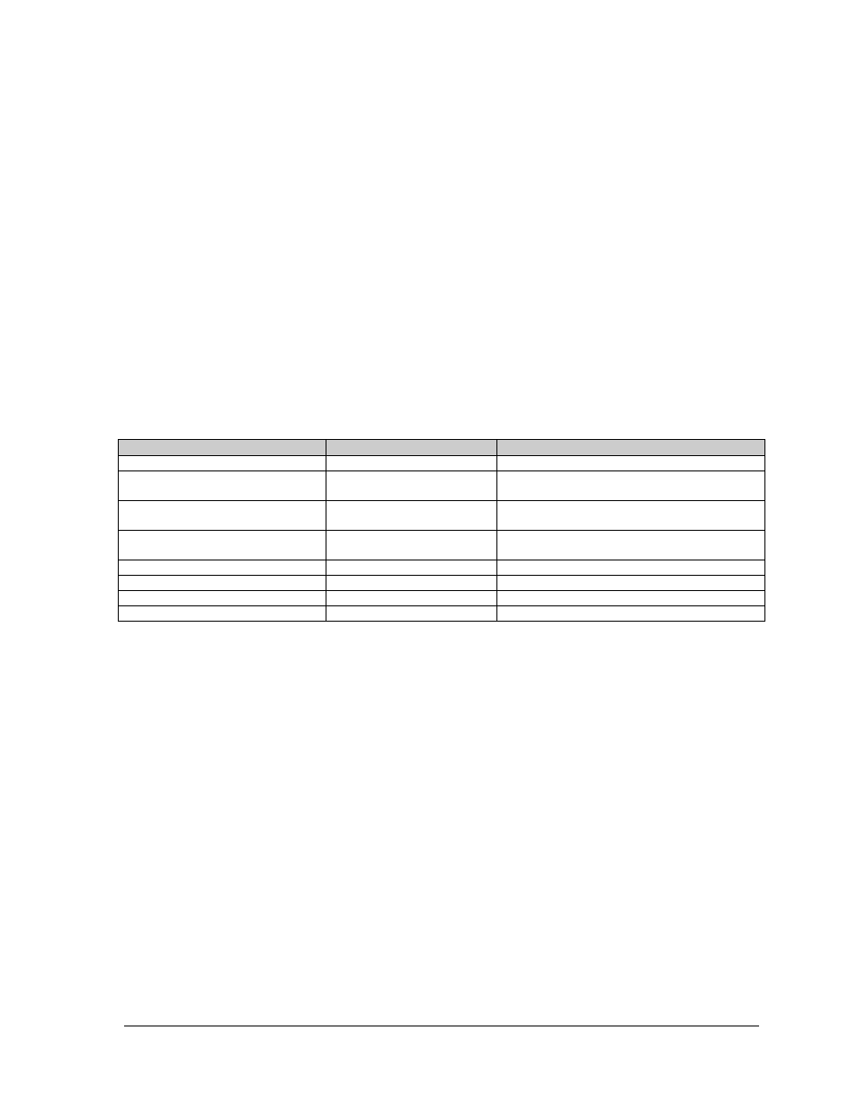
The sub-sections also address any diagnostic LEDs, fuses and signal/power connectors found on the unit. On
the Schematics and Component Layout Diagrams, the components are denoted as follows.
Component…
Denoted As…
Location…
Filter and Transformer
0A-1241-4005
Inside the power termination box
Controller
0A-1229-0001
Inside the controller/power panel (behind the
bottom left module)
Modules
Squares (0A-1208-2552)
A101 through A418
Over entire face of the display (includes
driver)
Power Supplies
0A-1241-4001
Behind modules (refer to your display’s
schematic)
Light Detector
0A-1241-4013
Behind\below the bottom left module
Modem
0P-1146-0003
Refer to the display’s schematic
Fiber Board
0P-1127-0024
Refer to the display’s schematic
RS422 Surge Card
0A-1241-4015
Refer to the display’s schematic