First time operation, 10 first time operation – Daktronics AF-3165-34-RGB User Manual
Page 34
Electrical Installation
30
Using more than 10 feet of cable, and no Quick Connect
1. Run ½" conduit from the sensor location to a knockout on the back of the first display. The
cable must be routed through ½" metal conduit that should be earth-grounded to protect the
sensor and controller from lightning damage.
2. Use a 2-pair, individually shielded cable (Belden 5594, Daktronics part number W-1234) to
connect the sensor to the controller.
3. Disconnect the CAN temp sensor cable from the temperature sensor terminal block in the
CAN temp sensor housing. (0A-1241-4017)
4. Connect the desired length of cable from the temperature terminal block in the CAN temp
sensor housing through conduit to the display.
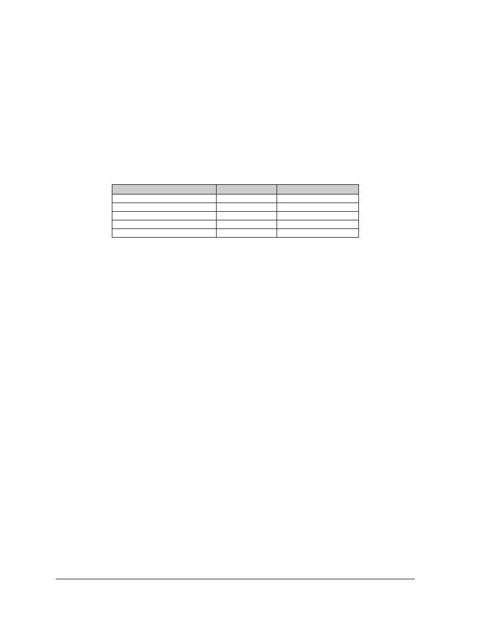
5. Terminate the cable to the 8-position terminal block in the display labeled “CAN US/DS”
(A35/TB4). Drawing A-175387 shows the terminal block wiring.
CAN Temp Sensor (TB1)
Field Cabling
CAN US (A35-TB4)
Pin 1 (+5V CAN)
Red
Pin 1 (+5V CAN)
Pin 2 (CAN H)
Green
Pin 2 (CAN H)
Pin 3 (CAN L)
White
Pin 3 (CAN L)
Pin 4 (GND CAN)
Black
Pin 4 (GND CAN)
Shield
Pin 5 (Shield)
3.10 First Time Operation
When first operated, the display will run through an initialization in which it will display the
following:
1. Product Name (Galaxy)
2. Display Size (Row x Column)
3. Shading (32,768 or 8)
4. Operating System (OS 3.XX)
5. Firmware Number (ED13305)
6. Firmware Revision (Rev X.XX)
7. Hardware Address (HW: XX)
8. Software Address (SW: XX)
9. IP Address (Not used at this time)
10. COM1 Configuration (C1: V15) or (Modem C1: V15), if modem is present.
11. Clock Mode (CLK:RTC)
12. Display Name