4 light sensor location – Daktronics DF-12xx User Manual
Page 28
3-6 Maintenance
and
Troubleshooting
1. The power LED (DS1) should remain lit while power is applied to the
modem.
2. The modem RX (DS3) and TX (DS4) LEDs are normally off, but will flash
when communicating.
3. The carrier detect LED (DS5) will light when the modem has established
communication to another modem.
The modem board also has several input and output jacks:
1. TB2 is a phoenix connector to terminate the Tip and Ring wires.
2. J3 is the AC power input into the modem board from the transformer in the
driver enclosure.
3. J6 is the RS232, RJ45 output jack from the modem board to the display
driver.
4. J5 is an RJ11 jack for termination of a pre-terminated phone line (if
needed).
5. J2, TB1, and TB3 are not used in this application.
3.4 Light Sensor Location
Reference Drawing:
Light Sensor Installation, G3 ....................................... Drawing A-183775
This display uses a light/photo sensor to regulate sign dimming functions. Use
Drawing A-183775 and the following instructions to replace the light sensor in your
DataMaster Gasoline Price display. If the sign or sign system has more than one
display, the light sensor is found in the host/primary display only.
1. Open the digit panel or display face panel.
2. Locate the
5
/
8
" sensor plughole on the front panel
of the display. The location of the plug varies by
model.
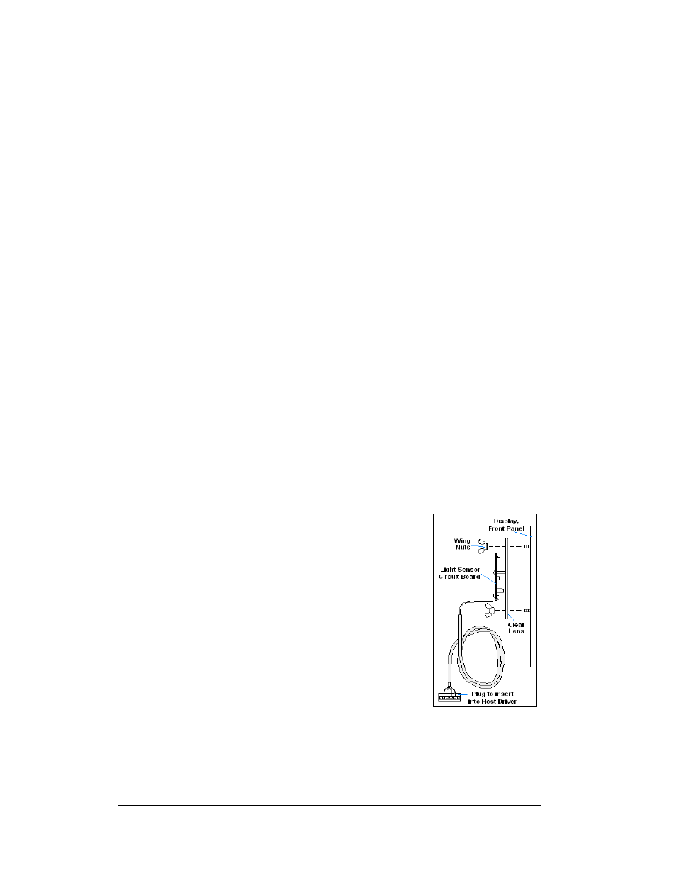
3. There are two 6-32 studs above and below the
plughole. The internal light sensor assembly
(Daktronics part #0A-1279-0203) is positioned on
the studs, with the clear lens toward the front of
the cabinet and the cable at the bottom. Secure the
sensor with the provided plastic wing nuts.
4. Route the signal cable to the driver and insert the
6-postion plug into the mating jack on the driver,
TB1.
5. Close the hinged access doors and replace the
screws.
Figure 15: Internal Light Sensor