Daktronics DF-12xx User Manual
Page 18
2-6 Electrical
Installation
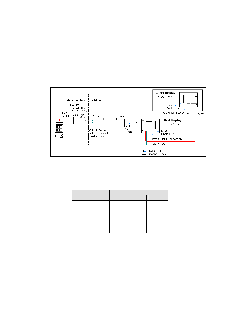
1. Using the DB9M to DB9F serial cable, connect from the DataMaster
controller to the J-box, at the “DB9 Male, DataMaster 100 connect” jack.
2. Using an 18-AWG, 6-conductor, shielded cable, (W-1370) connect from
the j-box jack labeled “RS422 to Radio or 422 Device” to the TB1 jack
on the Server radio, mounted to the building. See
Figure
5 and the table
below for cable connections from the j-box to the radio.
3. Plug the wall pack transformer into the j-box and then into a 120V
grounded outlet.
4. Mount the Client radio on the display or display pole, and within 25 feet
of the display.
5. Plug the quick connect cable from the client radio into the 6-pin quick
connect jack on the side of the Gas price display.
Connection from J-box to Server Radio Enclosure
J-Box
TB2 on Server
Pin#
Function
Cable
Color
Pin#
Function
Pin 1
Power
Red
Pin 1
Power
Pin 2
422 RX-P
White
Pin 2
422 TX-P
Pin 3
422 RX-N
Green
Pin 3
422 TX-N
Pin 4
422 TX-P
Brown
Pin 4
422 RX-P
Pin 5
422 TX-N
Blue
Pin 5
422 RX-N
Pin 6
GND
Black
Pin 6
GND
Notes:
1. The cable from the client radio to the display can to be routed through
conduit or the display pole to protect it from weather and vandalism. The
cable is weather and sunlight resistant.
2. The Server and Client radios must have a clear line-of-sight path and not
be more than 1500 feet apart.
Figure 4: Radio Controlled Display Layout