Client radio installation, Outdoor j-box installation, C. b. a – Daktronics Fuelight FL-3000 and FL-4500 Series 36 and 48 Petroleum Price Display and Cash/Credit Display User Manual
Page 25
Control Options Setup
19
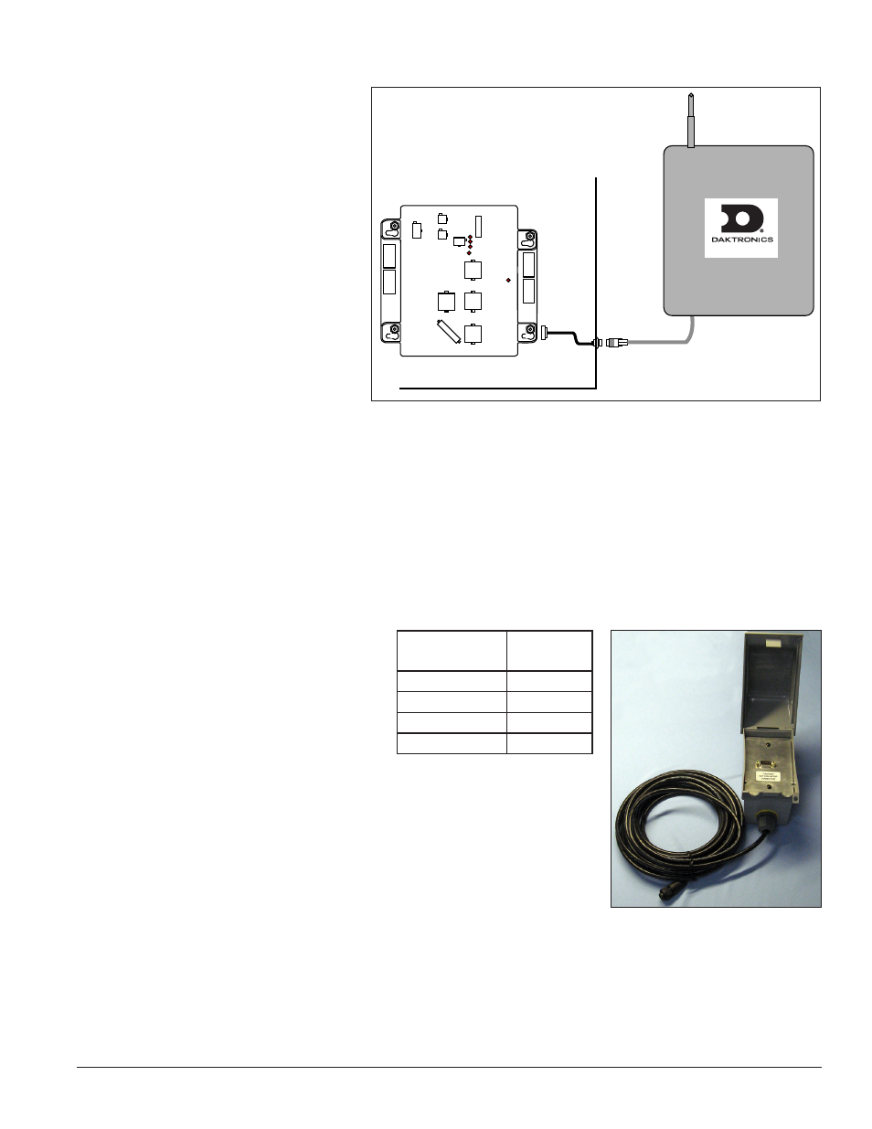
Client Radio Installation
1. Turn off power to the display
during the installation of the
radio.
2. Mount the client radio at or
within 25 feet (8 meters) of the
display.
3. Connect signal cables as follows.
The letter for each step is noted
in
a. Attach the 8-foot provided
cable to the host driver at
J16.
b. Attach the mating jack end
to the display cabinet. The
cable may be routed through
a conduit knockout in the
display to the side of the structure or shrouding. Use cable bushings to protect the cable from rough
edges.
c. Connect the quick-connect cable from the client radio to the mating jack at the display. The quick-
connect cable is pre-terminated in the client radio.
4. Secure loose cable to protect it from weather or vandalism.
Outdoor J-box Installation
1. Choose a location and attach the
on the support pole so it is easily
accessible for plugging in the
handheld controller. Mounting tabs
may be attached to the back of the
J-box with provided screws.
2. Orient the box so the quick-connect cable runs out the bottom of the
box.
3. Connect the unterminated end of the quick-connect cable inside the
outdoor J-box according to the chart at right.
4. Connect the 8-foot provided cable to J-16 on a display driver.
5. Route the cable through a knockout in the display and mount to the
side of the sign structure. Use cable bushings to protect cable from rough edges.
6. Connect the quick-connect cable from the J-box to the bulkhead connector on the side of the sign
structure.
POWER IN
24 DC
J14
DIGIT 4
J13
DIGIT 3
J12
DIGIT 2
J15
DECIMAL
J11
DIGIT 1
J18
J10
J9
J16
Inside Display Cabinet
Cable to
Driver
Quick-Connect
Cable From
Client Radio
C.
B.
A.
Client Radio
Figure 35: Client Radio Connections
Outdoor J-box
Terminal
Wire Color
TB3-1
Red
TB3-2
Green
TB3-3
White
TB3-4
Black
Figure 36: Outdoor J-box