2 access internal components, 3 grounding, 4 power installation – Daktronics Fuelight FL-3000 and FL-4500 Series 36 and 48 Petroleum Price Display and Cash/Credit Display User Manual
Page 14: Access internal components, 3 grounding 3.4, Power installation
8
Electrical Installation
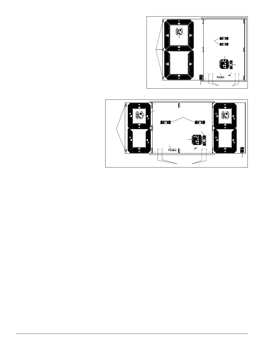
3.2 Access Internal Components
The door of Fuelight
™
Petroleum Price displays is
secured by two slotted fasteners.
1. Release the fasteners by gently turning them
counter-clockwise with a flat-head screwdriver.
2. Open the doors using the knobs attached to the
display faces.
3. Open doors without knobs by gently pushing
the door outward from inside of the display.
4. The driver and power supply(s) are attached
inside the cabinet to
the display’s backsheet
and their locations vary
between display sizes. See
Figure 8 and Figure 9 for
component locations.
5. A breakout board for each
digit is located between the
upper digit segments.
3.3 Grounding
FL-3000 and FL-4500 series
displays do not require a local
earth ground electrode.
The displays are designed so the most sensitive components are isolated and an earth ground is not required
and is no longer recommended.
The displays still require a safety ground from the electrical service panel for the primary power wires to
comply with national electric codes.
Please note that earth-grounding requirements for other Daktronics products remain unchanged.
3.4 Power Installation
Install Daktronics Fuelight
™
displays using the provided ground and neutral conductors. For this type of
installation, the power circuit must contain an isolated earth-ground conductor. Do not connect neutral to
ground at the disconnect or at the display, this would violate electrical codes and void the warranty. Use a
disconnect so that all ungrounded conductors can be disconnected.
To connect power to the display:
1. Route power cable into the display through one of the knockouts on the display’s backsheet.
2. Use wire nuts or other appropriate hardware to connect power wires to the power supply harness or
pigtail.
3. Connect supply power ground wire to ground bus bar.
Note: Verity the power supply ground wire is connected to the ground bus bar.
Driver
Driver
Power
Supply
Digit
Power
Supplies
Breakout
Board
Decimal Indicator
Knockouts
Ground Bar
Model
Number
Label
Latches
Figure 8: Internal Component Locations - 48-Inch Digits
Driver
Driver Power
Supply
Digit
Power
Supplies
Breakout
Board
Decimal
Indicator
Knockouts
Ground Bar
Model
Number
Label
Latches
Figure 9: Internal Component Locations - 36-Inch Digits