2 configure ingress traffic rate control – Contemporary Control Systems Compact Managed Switches Software Manual for Console Access User Manual
Page 46
TD020850-0MG
46
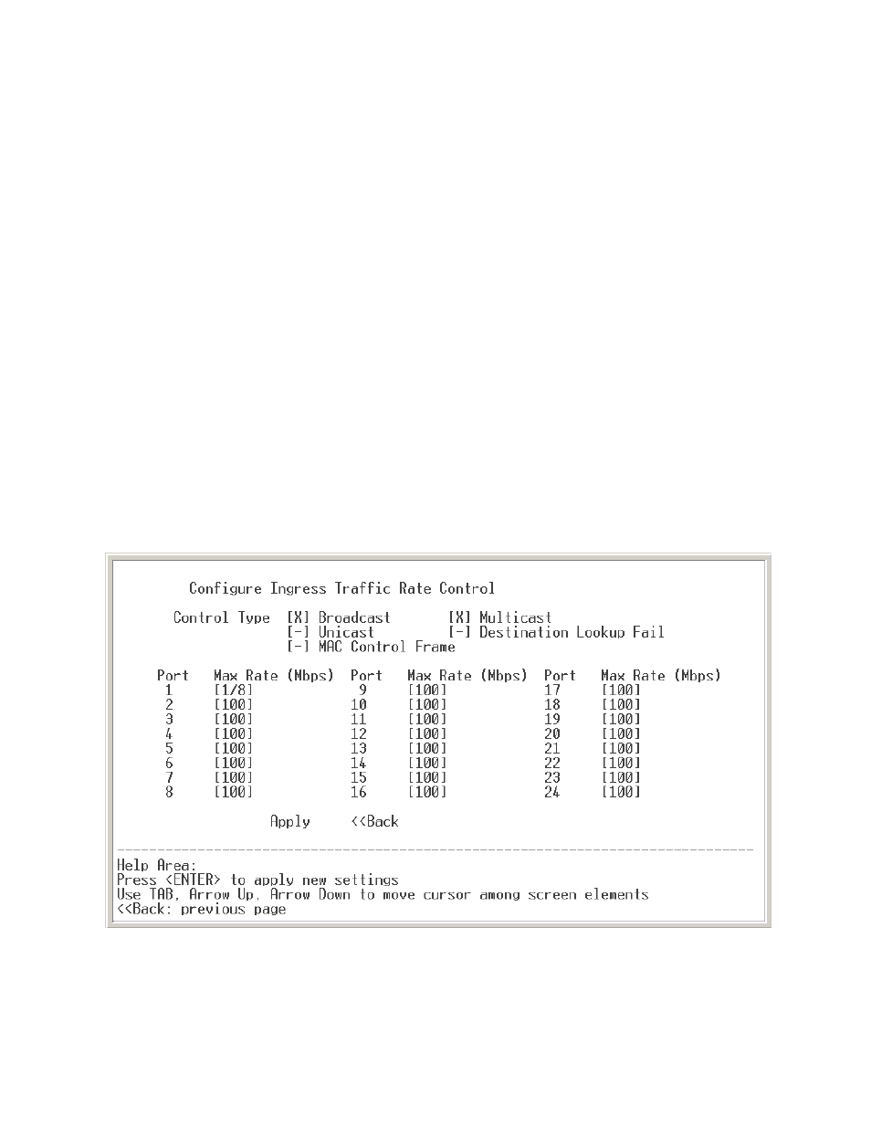
4.3.10.2 Configure Ingress Traffic Rate Control
Figure 37 shows a sample Configure Ingress Traffic Rate Control screen for a 24-port
switch. An 8-port switch or a 16-port switch will have screens that display only the
appropriate number of ports. Use your keyboard space bar to toggle through the
available options while the cursor is positioned in the field being modified.
The frame types that you can control are broadcast, multicast, unicast, destination
lookup fail, and MAC control frame. By placing all types under control, you can manage
the total bandwidth of the port in question. Selecting only broadcast frames effectively
creates a broadcast storm control that has a selectable maximum bandwidth setting. By
controlling the multicast traffic, you can limit the extent to which a group of devices can
consume bandwidth. On the other hand, if you deem group messaging more important,
you can control the traffic of unicast messages. Destination lookup fail frames are
merely unknown addresses — either never before encountered or those which have
been aged out of the MAC lookup table. MAC control frames are special frames — the
most common of which are PAUSE flow control frames.
In the example screen of Figure 37, rate control has been applied to broadcast and
multicast frames as indicated by an “X” in their respective fields.
The selected Max Rate is the maximum bandwidth level for the types of messages
selected. Types not selected will be allowed to use 100% of the port’s bandwidth.
NOTE: Port 1 in this example shows a Max Rate value set to “1/8”. This is 1/8 of a 1 Mbps
data rate — which is 128 kbps, the minimum value.
Figure 37 — Configure Ingress Traffic Rate Control