Comtech EF Data ROSS User Manual
Page 53
ROSS
MN/13070
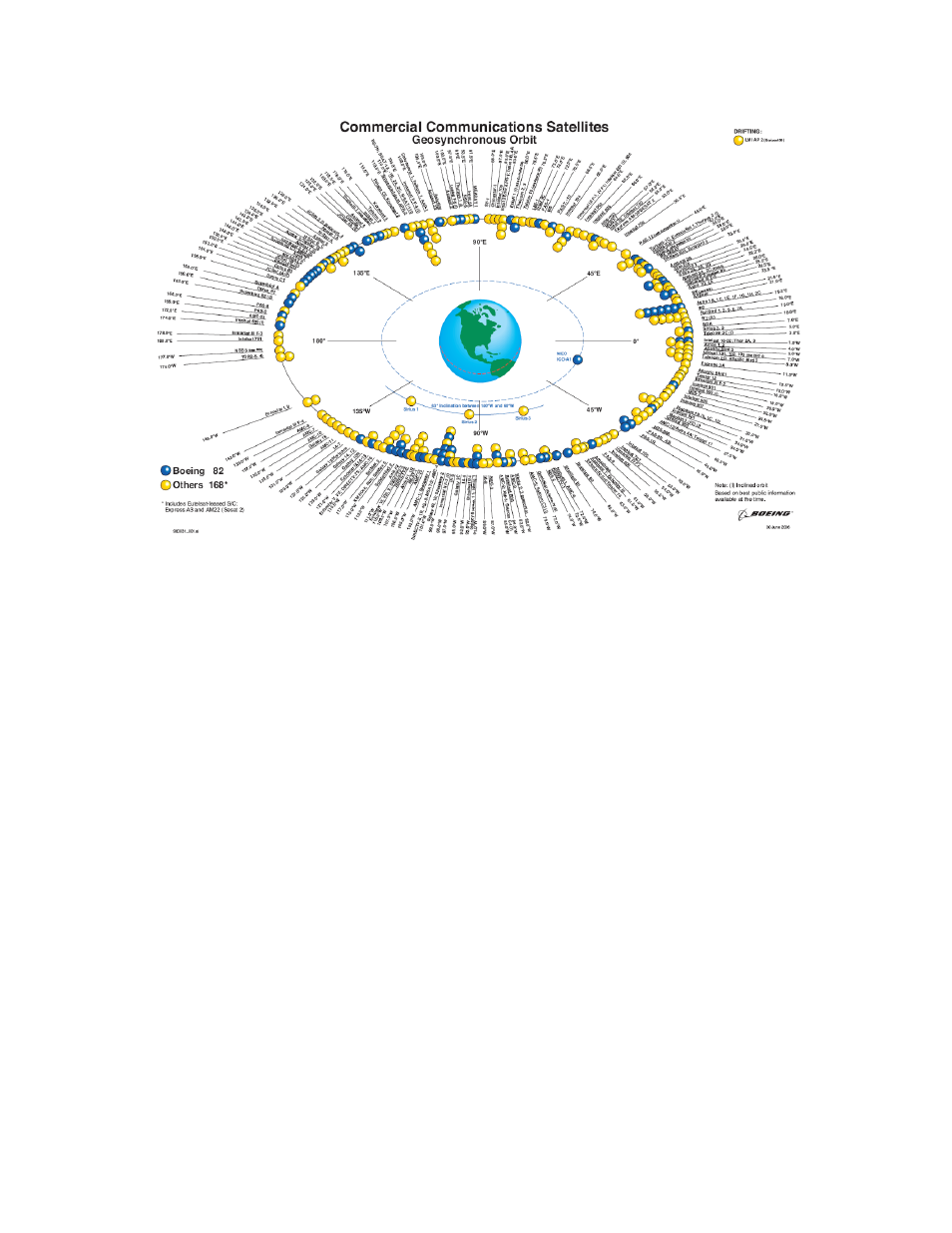
Figure 7: Orbital Position of Geosynchronous Satellites
2. Polarization – Transmit polarization is set for ‘None’ typically C-Band Global beams
or Vertical/Horizontal Ku-Band polarized feeds. This parameter is a dropdown list
dialog. This value is governed by the antenna hardware configuration and is set to
match the transmit transponder per service connection.
3. Frequency – The antenna controller requires a beacon carrier to track when
transitioning from cold start or beam to beam. This frequency value which is set in
MHz tunes the ACU’s receiver to a set center frequency to determine AGC thresholds
and peak tracking. Typically this frequency should match the TDM carrier for this
service area.
4. Bandwidth – The antenna controller requires a beacon carrier to track when
transitioning from cold start or beam to beam. This bandwidth value which is set KHz
tunes the ACU’s receiver to a set bandwidth to determine AGC thresholds. Typically
this bandwidth should match the TDM carrier for this service area. It is used in
conjunction with frequency setting.
5. Description - is only used as an assigned identification per service area configuration.
This assigned value is displayed within the ROSS view of service area menu.
6. Optional Settings – This field contains optional parameters values that are linked to
the ACU to provide additional RF controls. This is a text string that can change the
behavior of specific ROSS subsystems (i.e. ACU). Optional settings are linked to a
specific Service Area.
Comtech EF Data, Vipersat Products
Page 53 of 87