3 crs-150 switch dip settings – Comtech EF Data CRS-150 User Manual
Page 64
CRS-150 1:1 Redundancy Switch
Revision 1
Modem and Switch Configuration MN/CRS150.IOM
5–4
“Switch Mode” DIP Switches
5.3
CRS-150 Switch DIP Settings
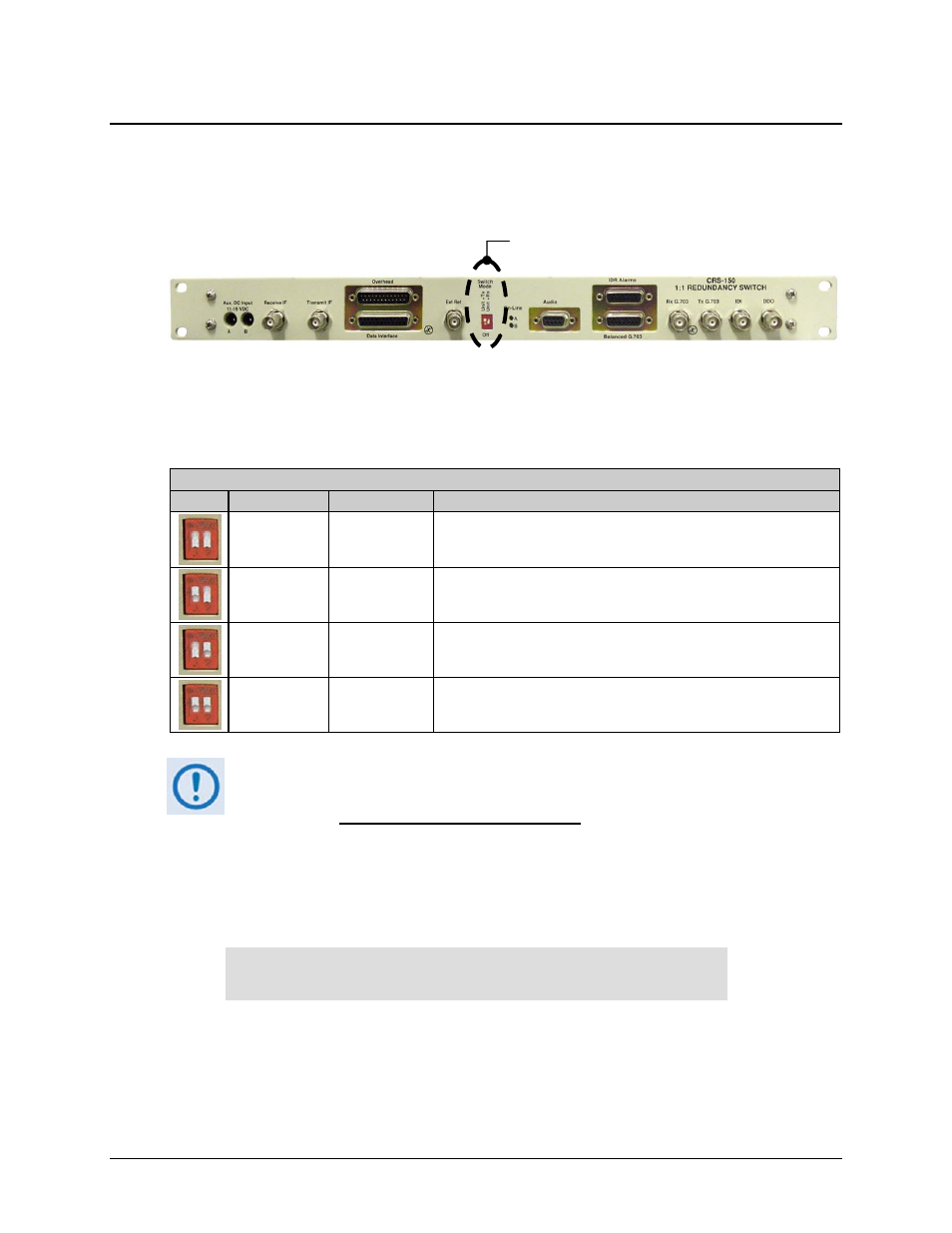
Two configuration switches are provided on the front panel of the CRS-150 L-Band 1:1
Redundancy Switch (see Figure 5-2). These ‘Switch Mode’ DIP switches control the conditions
that initiate an automatic switchover.
Figure 5-2. CRS-150 Front Panel – DIP Switches
Table 5-1 illustrates the settings for the ‘Switch Mode’ DIP switch settings that determine
switchover functionality for a given redundancy configuration.
Table 5-1. CRS-150 DIP Switch Settings
‘Switch Mode’ DIP Settings
DIP
Left Switch
Right Switch
Result
Down (Off)
Down
Switchover upon a Unit fault only
Up
Down
Switchover upon a Unit or Tx Traffic fault
Down
Up
Switchover upon a Unit or Rx Traffic fault
Up
Up
Switchover upon a Unit or Tx Traffic or Rx Traffic fault
RECOMMENDATION:
Comtech EF Data recommends that for most applications, the CRS-150 should be
configured for Switchover upon a Unit fault only.
Once switchover functionality has been assigned, the modems in redundancy handle faults and
alarms based on the combination of the ‘Switch Mode’ DIP settings, and how faults and alarms are
handled by the modems,as configured using the (Select:) INFORMATION: ALARM-MASK
menu via the CDM-600 front panel:
ALARMS MASKED: TX-AIS RX-AIS BUF-SLIP
AGC EBNO SAT TERR
This modem screen shows only any alarm(s) designated as currently masked; if an alarm is not
masked, the relevant screen position of that feature is replaced with a blank space. For detailed
information on possible fault conditions and alarm masking in general, see Chapter 5. FRONT
PANEL OPERATION in the CDM-600/600L Satellite Modem Installation and Operation
Manual.