Comtech EF Data CRS-150 User Manual
Page 51
CRS-150 1:1 Redundancy Switch
Revision 2
Cables and Connections
MN/CRS150.IOM
4–7
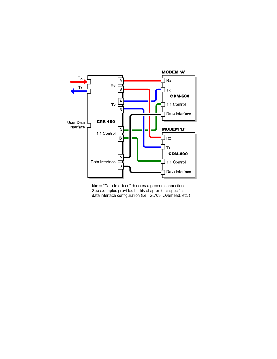
4.2.5 Modem-to-User Data Interface Connection and Examples
Aside from control, IF, and utility switch-to-modem cabling shown previously, there are a
number of data interface configurations available with the CDM-600. The block diagram shown
in Figure 4-5 is typical for the examples shown in Sects. 4.2.5.1 through 4.2.5.9.
Figure 4-5. CDM-600 Block Diagram: User
Æ Modem Æ Switch Æ Traffic
Note: Unless otherwise specified, the interface cables and components identified in each of the
following examples are individually available for purchase (See Sect. 4.2). For each user interface,
one cable/component set per 1:1 modem pair is required (see examples for specified quantities).
- CDD-880 (124 pages)
- CDM-800 (130 pages)
- ODMR-840 (184 pages)
- CDM-750 (302 pages)
- CDM-840 (244 pages)
- SLM-5650A (420 pages)
- CTOG-250 (236 pages)
- CDM-700 (256 pages)
- CDM-760 (416 pages)
- CDM-710G (246 pages)
- CDM-600/600L (278 pages)
- CDMR-570L (512 pages)
- CDM-625 (684 pages)
- CDM-625A (756 pages)
- CDD-564A (240 pages)
- CDD-564L (254 pages)
- CLO-10 (134 pages)
- MCED-100 (96 pages)
- CDMR-570AL (618 pages)
- CDM-600 LDPC (2 pages)
- BUC Power Supply Ground Cable (2 pages)
- MPP70 Hardware Kit for CDM-570L (4 pages)
- MPP50 Hardware Kit for CDM-570L (4 pages)
- CDM-625 DC-AC Conversion (4 pages)
- CDM-625 DC-AC Conversion with IP Packet Processor (4 pages)
- DMDVR20 LBST Rev 1.1 (117 pages)
- DMD2050E (212 pages)
- DMD-2050 (342 pages)
- DMD1050 (188 pages)
- OM20 (220 pages)
- QAM256 (87 pages)
- DD240XR Rev Е (121 pages)
- MM200 ASI Field (5 pages)
- DM240-DVB (196 pages)
- MM200 (192 pages)
- CRS-280L (64 pages)
- CRS-170A (172 pages)
- CRS-180 (136 pages)
- SMS-301 (124 pages)
- CiM-25/8000 (186 pages)
- CiM-25 (26 pages)
- CRS-500 (218 pages)
- CRS-311 (196 pages)
- CIC-20 LVDS to HSSI (26 pages)