Chapter 3. connector pinouts, 1 connector overview – Comtech EF Data CRS-150 User Manual
Page 27
3–1
Chapter 3. CONNECTOR PINOUTS
3.1 Connector Overview
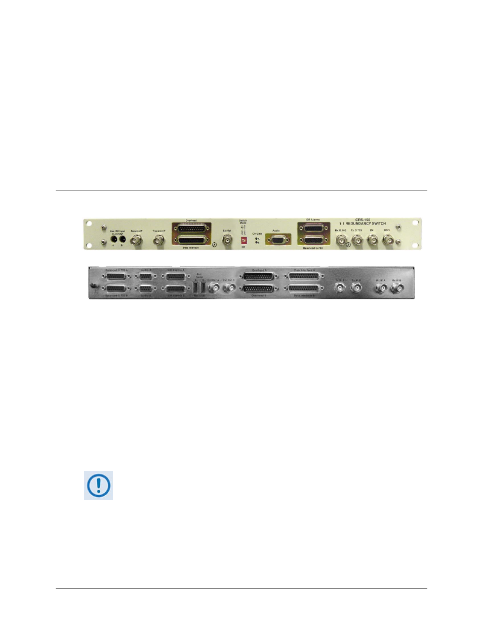
Front Panel View
Rear Panel View
Figure 3-1. CRS-150 Connectors
The front and rear panels of the CRS-150 1:1 Redundancy Switch are shown in Figure 3-1.
The front panel connectors provide all necessary to connect all equipment external to the 1:1
redundancy setup. The rear panel connectors of the CRS-150 1:1 Redundancy Switch provide all
the connections between the CRS-150 and the two CDM-600 modems in the 1:1 pair.
Also optionally available are two interface converter modules: The CIC-20, which converts
LVDS to HSSI, and the CIC-35, which converts LVDS to ASI. Full information on either of
these products is available from their respective operation manuals; for the purpose of this
chapter, only the User Data Interface pinouts are documented.
On the next page, Table 3-1 summarizes these connectors, grouped according to location (front,
rear, or data interface) and service function.
The European EMC Directive (EN55022, EN50082-1) requires using properly
shielded cables for DATA I/O. These cables must be double-shielded from
end-to-end, ensuring a continuous ground shield.