2 rack-mounting the crs-150 – Comtech EF Data CRS-150 User Manual
Page 26
CRS-150 1:1 Redundancy Switch
Revision 2
Installation
MN/CRS150.IOM
2–2
3
Inspect the equipment for any possible damage incurred during shipment. Contact the
carrier and Comtech EF Data immediately to submit a damage report if damage is evident.
4
Review the Installation and Operation Manual carefully to become familiar
with operation.
5
Proceed to Section 2.2 Rack-Mounting the CRS-150.
2.2
Rack-Mounting the CRS-150
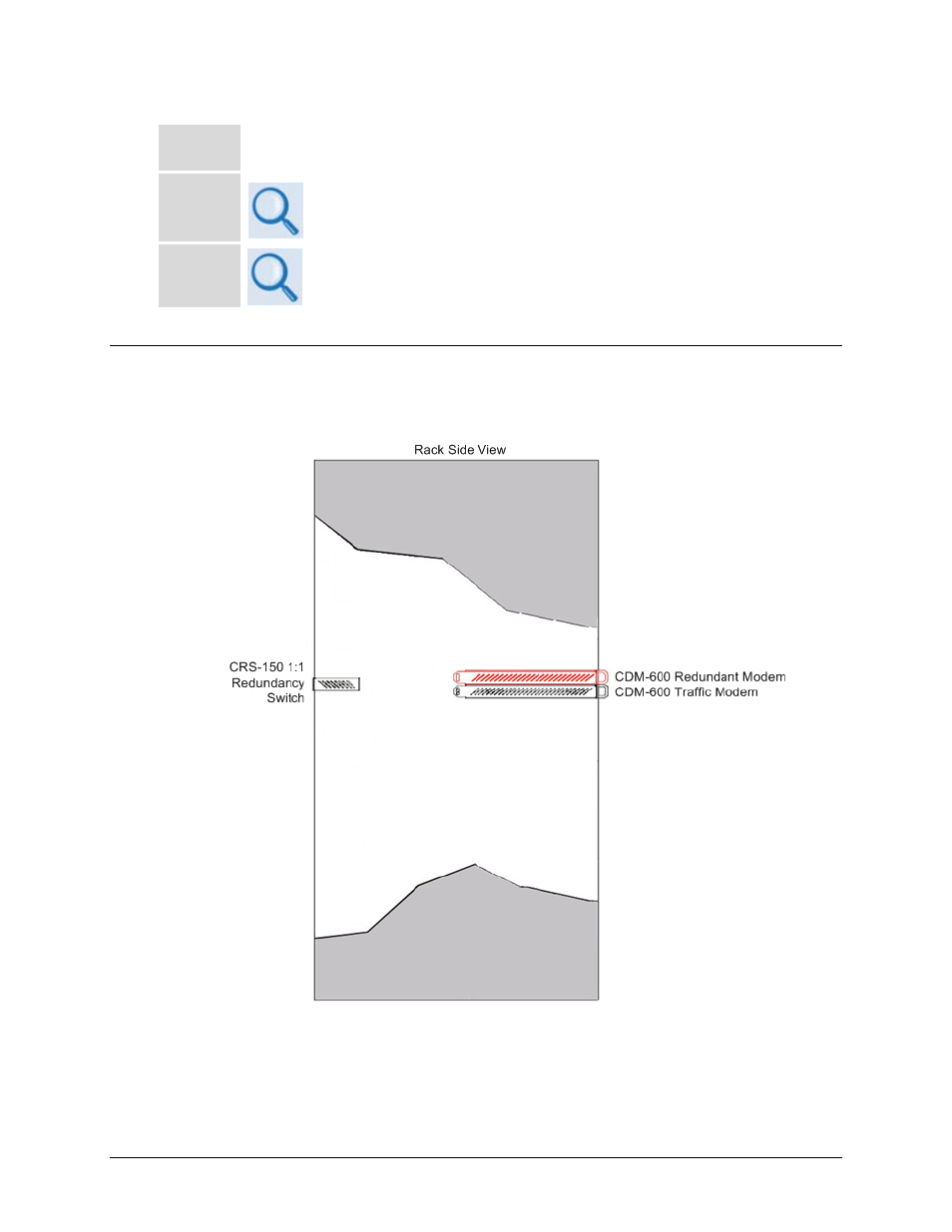
The CRS-150 is designed to be mounted into the rear of a rack, behind the CDM-600 modems.
This typical configuration is shown in Figure 2-1.
Figure 2-2. Typical CDM-600/CRS-150 1:1 Redundancy Installation
Once the CRS-150 has been installed into operating position, it will be ready for configuration and
cabling connections. Please refer to Chapter 4. MODEM AND SWITCH CONFIGURATION
and Chapter 5. CABLES AND CONNECTIONS for further information.
- CDD-880 (124 pages)
- CDM-800 (130 pages)
- ODMR-840 (184 pages)
- CDM-750 (302 pages)
- CDM-840 (244 pages)
- SLM-5650A (420 pages)
- CTOG-250 (236 pages)
- CDM-700 (256 pages)
- CDM-760 (416 pages)
- CDM-710G (246 pages)
- CDM-600/600L (278 pages)
- CDMR-570L (512 pages)
- CDM-625 (684 pages)
- CDM-625A (756 pages)
- CDD-564A (240 pages)
- CDD-564L (254 pages)
- CLO-10 (134 pages)
- MCED-100 (96 pages)
- CDMR-570AL (618 pages)
- CDM-600 LDPC (2 pages)
- BUC Power Supply Ground Cable (2 pages)
- MPP70 Hardware Kit for CDM-570L (4 pages)
- MPP50 Hardware Kit for CDM-570L (4 pages)
- CDM-625 DC-AC Conversion (4 pages)
- CDM-625 DC-AC Conversion with IP Packet Processor (4 pages)
- DMDVR20 LBST Rev 1.1 (117 pages)
- DMD2050E (212 pages)
- DMD-2050 (342 pages)
- DMD1050 (188 pages)
- OM20 (220 pages)
- QAM256 (87 pages)
- DD240XR Rev Е (121 pages)
- MM200 ASI Field (5 pages)
- DM240-DVB (196 pages)
- MM200 (192 pages)
- CRS-280L (64 pages)
- CRS-170A (172 pages)
- CRS-180 (136 pages)
- SMS-301 (124 pages)
- CiM-25/8000 (186 pages)
- CiM-25 (26 pages)
- CRS-500 (218 pages)
- CRS-311 (196 pages)
- CIC-20 LVDS to HSSI (26 pages)