2 rear panel terrestrial data connectors, Balanced g.703 a and b connectors, db-15m – Comtech EF Data CRS-150 User Manual
Page 36
CRS-150 1:1 Redundancy Switch
Revision 2
Connector Pinouts
MN/CRS150.IOM
3–10
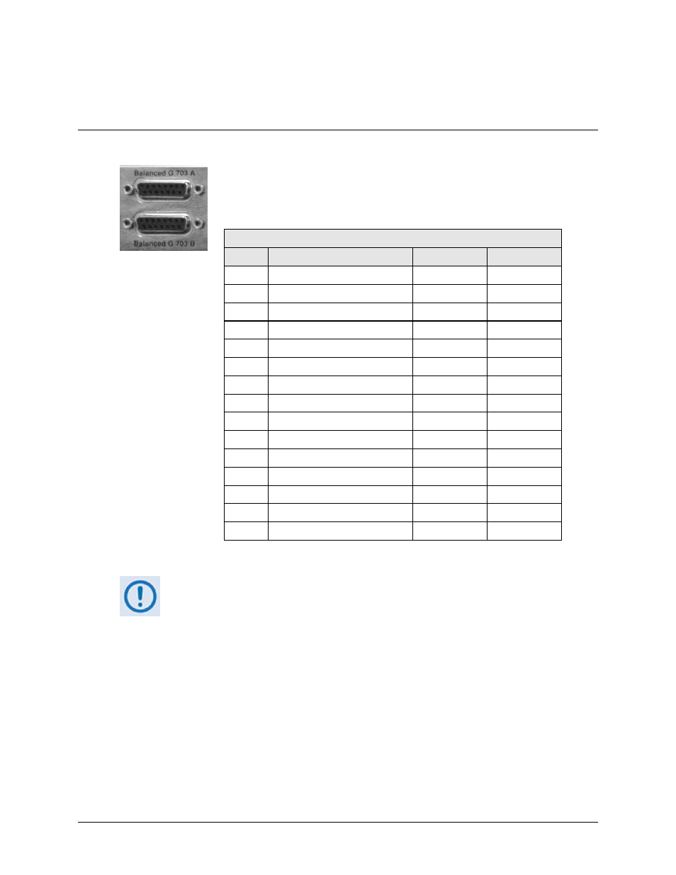
3.3.2 Rear Panel Terrestrial Data Connectors
3.3.2.1 Balanced G.703 A and B Connectors, DB-15M
The 15-pin ‘D’ Type female (DB-15F) Balanced G.703 A and B connectors
are used for balanced operation at the G.703 data rates of T1 (1.544 Mbps),
E1 (2.048 Mbps), or T2 (6.312 Mbps).
Balanced G.703 A and B Connectors (DB-15F)
Pin #
Signal Function
Name
Direction
1*
Drop Data Input ( - )
DDI–
Out
9*
Drop Data Input (+)
DDI+
Out
2 Ground GND
10 Not
Used
3*
Insert Data Output ( - )
IDO–
In
11*
Insert Data Output (+)
IDO+
In
4 Ground GND
12
Drop Data Output ( - )
DDO–
In
5
Drop Data Output (+)
DDO+
In
13
Insert Data Input ( - )
IDI–
Out
6
Insert Data Input (+)
IDI+
Out
14 Not
Used
7 Not
Used
15 Not
Used
8 Not
Used
*Use for all non-Drop and Insert and T2/E2 balanced applications.
In order to simplify the cabling between the CDM-600 modems and the CRS-150
Redundancy Switch, all G.703 signals are carried between modems and switch
on the BALANCED connections, regardless of the choice of balanced/
unbalanced connectors on the CRS-150 front panel.
The user should not be concerned about this – the modem signals the
appropriate port type (balanced or unbalanced) to the CRS-150, so correct
operation of the ports is assured.