2 front panel connectors – Comtech EF Data CRS-150 User Manual
Page 29
CRS-150 1:1 Redundancy Switch
Revision 2
Connector Pinouts
MN/CRS150.IOM
3–3
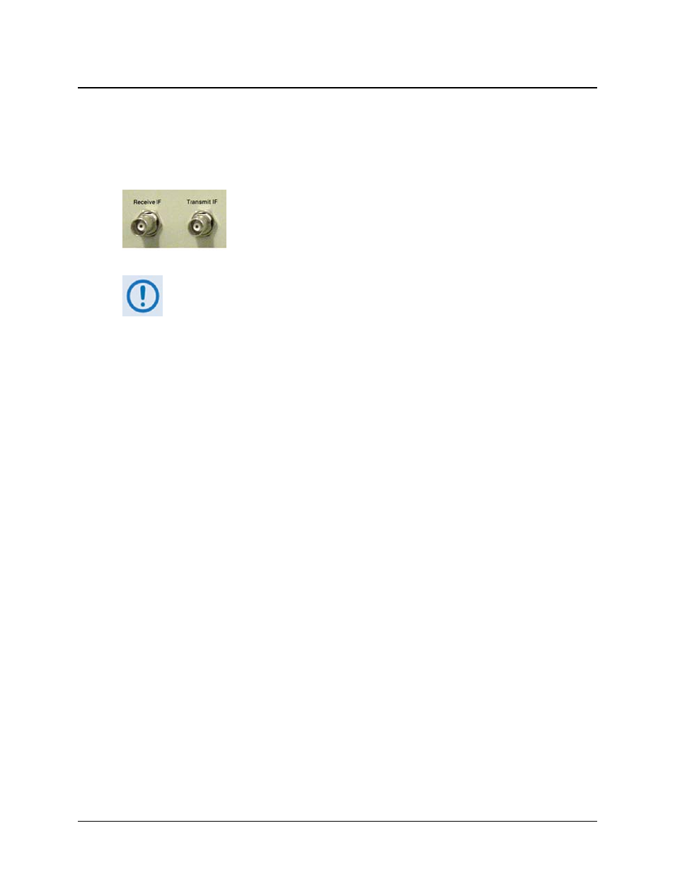
3.2 Front Panel Connectors
Unless otherwise noted, the connectors featured on the front panel of the CRS-150 are intended
for connection to all equipment external to the 1:1 redundancy setup.
3.2.1 Front Panel IF Connectors – Receive IF and Transmit IF, 50Ω BNC
The Receive IF and Transmit IF port connectors are both 50
Ω Type
‘BNC’ female. The electrical impedance presented by these connectors is
controlled internally by an RF-switching arrangement – this selection
between 50
Ω and 75Ω is controlled either via the CDM-600 front panel
menus, or via the CDM-600 remote control bus.
The CRS-150 has been optimized to work with 50Ω systems, and it is very
important that 50Ω cables are used between the CRS-150 and the traffic
modems. For users with a 75Ω system, 50Ω-to-75Ω transformers are supplied
with the CRS-150 that should be connected to the external IF ports.