3 cabling to the cdm-600l (clm-9600l) – Comtech EF Data CRS-150 User Manual
Page 60
CRS-150 1:1 Redundancy Switch
Revision 2
Cables and Connections
MN/CRS150.IOM
4–16
4.3
Cabling to the CDM-600L (CLM-9600L)
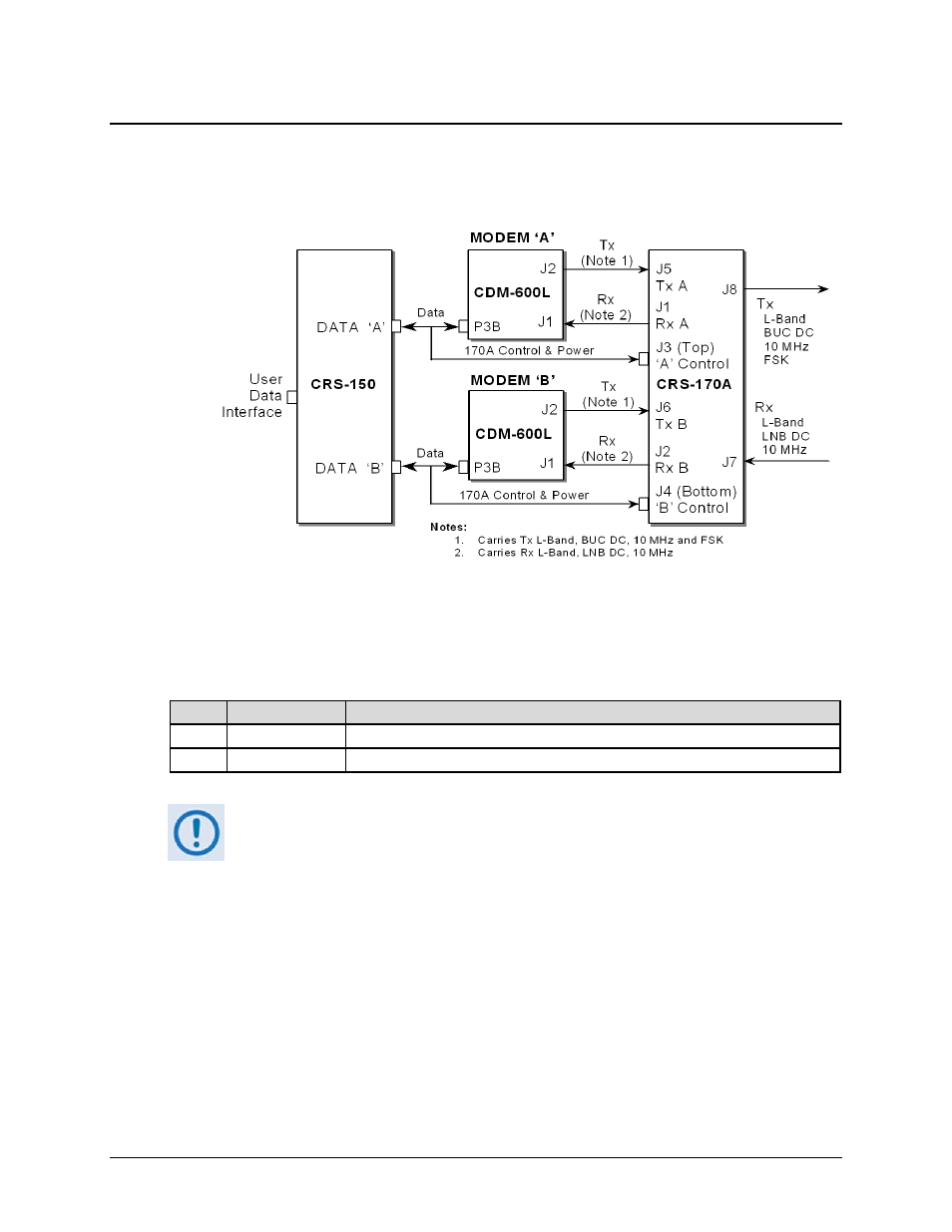
The block diagram shown in Figure 4-14 depicts connection of a pair of CDM-600L (CLM-9600L)
modems together with the CRS-150 and CRS-170A switches.
Figure 4-14. CDM-600L (CLM-9600L) Block Diagram: Cable Connections
The following table lists cable assemblies that may be supplied with the CRS-170A when used
with the CDM-600L (CLM-9600L) and CRS-150. Other cables between the CRS-150 and the
CDM-600L (CLM-9600L) modems are supplied with the CRS-150.
QTY
Part No.
Description
2
CA/WR10456-4
Cable – 1:1 Y-Splitter, Data/Control, DB-25M Æ DB-25M, 4’ / DB-9M, 1’
4
CA/RF10453-4
RoHS-Compliant Cable – IF (Tx/Rx), 50Ω Type ‘N’, 4’
When connecting the Control cable between the CRS-150 and the modems,
ensure that screw locks on the ‘D’ type connectors are securely fastened. This
will prevent the accidental un-mating of the cable, particularly when a standby
unit is being removed or replaced.