3 rear panel utility connectors, 1 idr alarms a and b connectors, db-15f, 2 aux serial a and b receptacles, usb type ‘a – Comtech EF Data CRS-150 User Manual
Page 40
CRS-150 1:1 Redundancy Switch
Revision 2
Connector Pinouts
MN/CRS150.IOM
3–14
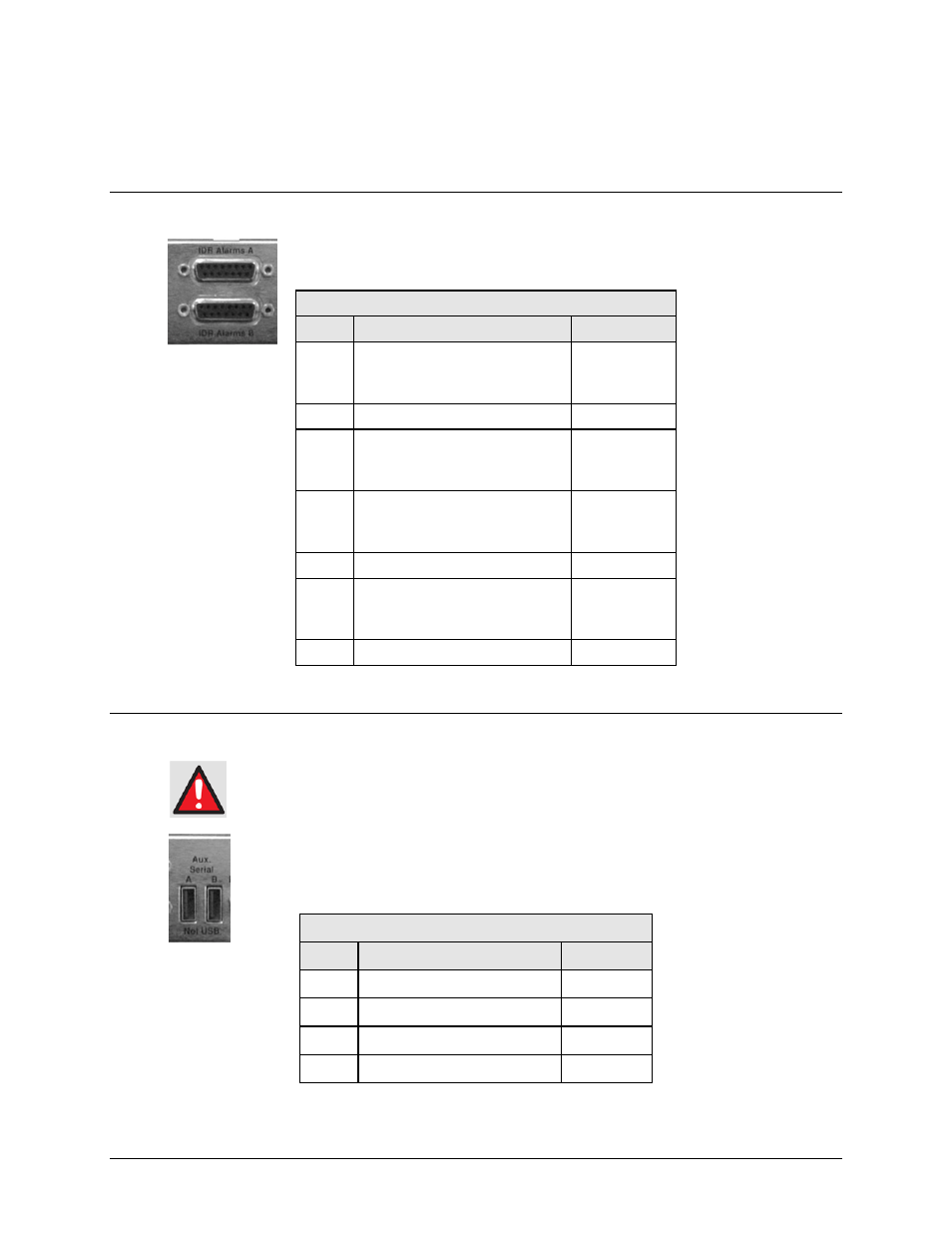
3.3.3 Rear Panel Utility Connectors
3.3.3.1 IDR Alarms A and B Connectors, DB-15F
The 15-pin Type ‘D’ female (DB-15F) IDR Alarms A and B interface connectors
provide four Form-C backward alarm outputs specified by Intelsat.
3.3.3.2 Aux Serial A and B Receptacles, USB Type ‘A’
Although these ports use USB connectors, the signals are
not USB-compatible.
DO NOT connect either of these ports to the USB port of a PC or other
computing device.
The USB Type ‘A’ Aux Serial A and B receptacles are additional EIA-232 serial
ports, connected to the modem’s USB Type ‘B’ Aux Serial ports when part of a 1:1
redundant pair.
IDR Alarms A and B Connectors (DB-15F)
Pin #
Signal Function
Name
2
9
1
Backward Alarm 1 is active
Backward Alarm 1 is not active
BA-1-NO
BA-1-COM
BA-1-NC
10 TBD
MON-A
4
11
3
Backward Alarm 2 is active
Backward Alarm 2 is not active
BA-2-NO
BA-2-COM
BA-2-NC
6
13
5
Backward Alarm 3 is active
Backward Alarm 3 is not active
BA-3-NO
BA-3-COM
BA-3-NC
14 TBD
MON-B
8
15
7
Backward Alarm 4 is active
Backward Alarm 4 is not active
BA-4-NO
BA-4-COM
BA-4-NC
12 Ground
GND
Aux Serial Receptacles A and B (USB Type ‘A’)
Pin #
Description
Direction
1 Ground --
2
EIA-232 TX Data
Out
3
EIA-232 RX Data
In
4 Ground --