3 rear panel connectors – Comtech EF Data CRS-150 User Manual
Page 35
CRS-150 1:1 Redundancy Switch
Revision 2
Connector Pinouts
MN/CRS150.IOM
3–9
3.3 Rear Panel Connectors
The rear panel connectors of the CRS-150 1:1 Redundancy Switch provide all the connections
between the CRS-150 and the two CDM-600 modems in the 1:1 pair.
With the exception of the mandatory main connections between the 25-pin data
ports (Overhead A/B, Data Interface A/B), the remaining connections are purely
optional.
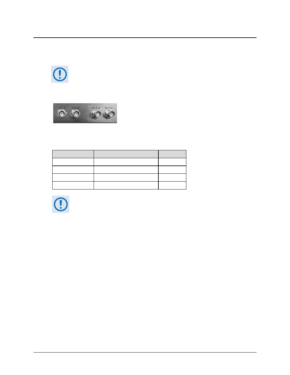
3.3.1 Rear Panel IF Connectors – Receive IF and Transmit IF A/B, 50Ω BNC
The Receive IF and Transmit IF A and B port connectors are all
50
Ω Type ‘BNC’ female. The electrical impedance presented
by these connectors is controlled internally by an RF-switching
arrangement – this selection between 50
Ω and 75Ω is controlled
either via the CDM-600 front panel menus, or via the CDM-600
remote control bus.
Observe the following:
BNC Connector
Description
Direction
Tx IF A
RF Input
In
Tx IF B
RF Input
In
Rx IF A
RF Output
Out
Rx IF B
RF Output
Out
The CRS-150 has been optimized to work with 50Ω systems, and it is very
important that 50Ω cables are used between the CRS-150 and the traffic
modems. For users with a 75Ω system, 50Ω-to-75Ω transformers are supplied
with the CRS-150 that should be connected to the external IF ports.