Rear panel interfaces, 0 dmdvr20 lbst connections, 1 compact flash – Comtech EF Data DMDVR20 LBST Rev 1.1 User Manual
Page 70
DMDVR20 LBST Satellite Modem
Rear Panel Interfaces
TM136 – Rev. 1.1
5-1
Rear Panel Interfaces
5
This section discusses the electrical interfaces available from the rear panel. All locations are as
viewed from the rear of the unit unless otherwise specified.
5.0 DMDVR20 LBST Connections
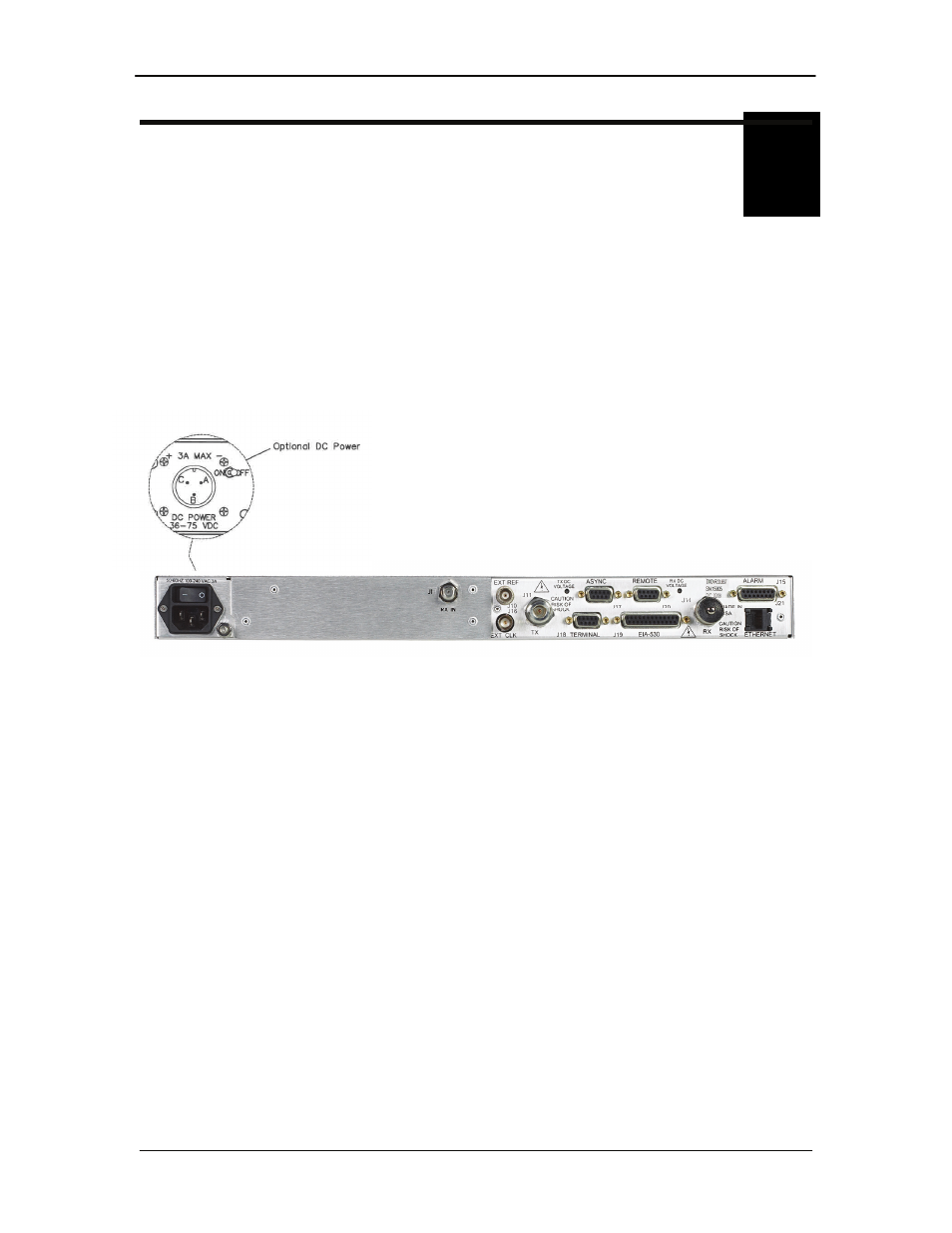
All DMDVR20 LBST connections are made to labeled connectors located on the rear of the unit
(refer to Figure 5-1 for the DMDVR20 LBST. The connector definitions below are those on the
DMDVR20 LBST unit. Any connection interfacing to the DMDVR20 LBST must be the
appropriate mating connector.
Figure 5-1. DMDVR20 LBST Satellite Modem Rear Panel Configurations
5.1 Compact Flash
The compact flash slot is located on the right side as viewed from the rear of the unit. A 128 or
256 Mbit flash memory card that stores all the modem M&C and operational data. It must be
present when the modem is operating.