Theory of operation, 0 modem hardware, 1 l-band printed circuit card – Comtech EF Data DMDVR20 LBST Rev 1.1 User Manual
Page 22
DMDVR20 LBST Satellite Modem
Theory of Operation
TM136 – Rev. 1.1
3-1
Theory of Operation
3
3.0 Modem Hardware
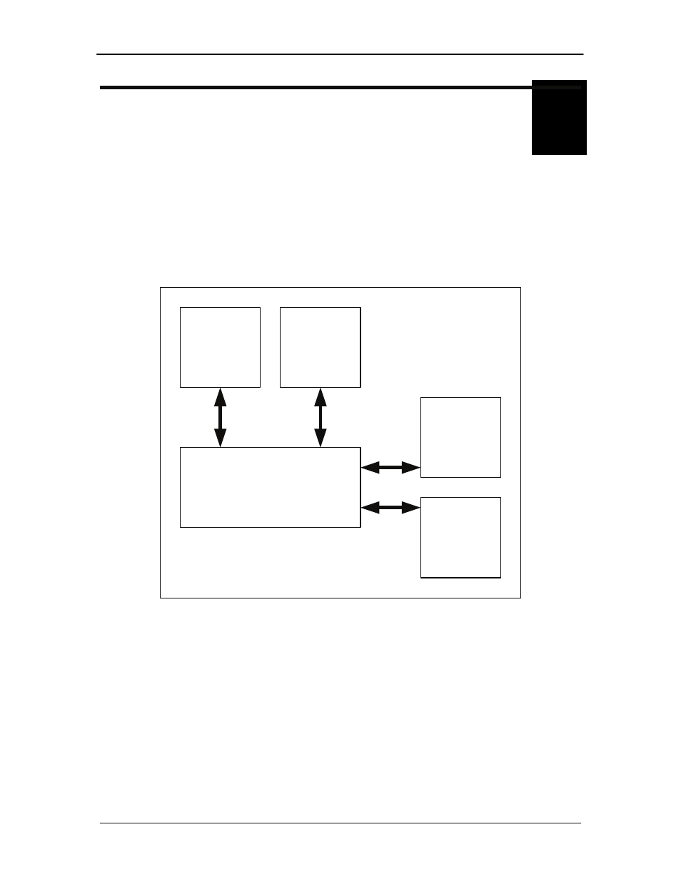
The modem is based on a two printed circuit card (minimum configuration) design with additional
optioned printed circuit cards available for additional features. The minimum configuration
consists of a Digital Baseband assembly, Tx L-Band assembly and RX L-Band Receiver
assembly. The optional printed circuit cards include a Turbo Codec printed circuit card an
optional data interface printed circuit card (refer to Appendix A). A block diagram of the Modem is
shown in Figure 3.1.
Digital Baseband
Card
Rx L-Band
LDPC
IF Card
Tx L-Band
IF Card
Interface
Card
(Optional)
Tx Turbo
Card
(Optional)
Cable
Cable
Cables
Figure 3-1. Block Diagram
3.0.1 L-Band Printed Circuit Card
The L-Band circuit cards consists of an analog modulation function, an analog complex down
conversion, and two wide-band digital synthesizers. The block diagram of the L-Band assembly
is shown in Figure 3-2.
In the modulator, analog in-phase (I) and quadrature (Q) signals are generated on the Digital
Baseband Printed Circuit Card, routed to the L-Band Printed Circuit Card, and modulated at the
desired frequency. The L-Band modulated signal is then passed through a microprocessor
controlled variable attenuator providing gain control of the output signal.