Cb 1 series, Administrator guide – Code Blue CB 1-E ECONOMICAL HELP POINT User Manual
Page 52
Code Blue
•
259 Hedcor Street
•
Holland, MI 49423 USA
•
800.205.7186
•
www.codeblue.com
GU-157-E
page 52 of 71
CB 1 Series
Administrator Guide
CALLOUTS
1. Low Voltage Strobe (#10620) or LED Beacon/
Strobe (#41070)
2. HPS or Metal Halide fixture, 120V AC only
3. LED Faceplate Light (#10921)
4. Faceplate/speakerphone electronics
5. Power Panel w/Terminal JBox Block & 120-
24V Transformer
6. Phone Line Surge Suppressor w/Ground Wire
for earth ground
PARTS LIST
• (1) #11804, A-700 LED Area Light
• (1) #11950, Red/Black Wire Harness
The following instructions pertain to modifying
high voltage HPS/Metal Halide fixtures to A-700
LED low voltage area light
1. Disconnect power to the unit
2. Remove Dome Top Lens, then loosen the
three thumb screws on the lower inside edge
of the metal casting
3. Lift casting and unplug strobe light wiring
4. Secure wires, so they don’t fall down inside
the unit
5. Lift reflector plate from enclosure
6. Lift light fixture, locating the power cable and
unplug; remove light out of the unit
7. Disconnect HPS/Metal Halide light power
cable from the 120 volt side of the transform-
ers
8. Grab the power cable at the top of the unit
and cut the zip tie holding it to the cross
member
9. Fully remove cable out of unit
10. Install the new LED area light with a plug-in
wire harness (part #11950)
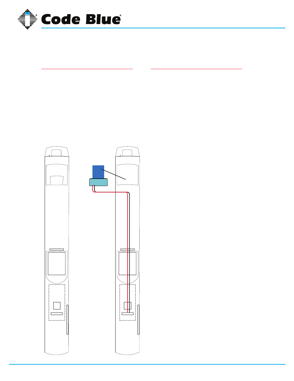
11. These wires will connect to the terminal strip
as illustrated in the wiring diagram
12. Replace reflector plate and reconnect the
strobe light
13. Line up the casting and tighten thumb
screws
14. Replace clear lens and secure with button
head screws removed earlier
14. WIRING: Follow the low voltage wiring
diagram. The red wire goes on terminal #4
and black to terminal #7 as shown in Wire
Diagram 3.
15. Reapply power and test
UPGRADING CURRENT AREA LIGHT TO A-700 LED
Fig. 4