Cb 1 series, Administrator guide – Code Blue CB 1-E ECONOMICAL HELP POINT User Manual
Page 43
Code Blue
•
259 Hedcor Street
•
Holland, MI 49423 USA
•
800.205.7186
•
www.codeblue.com
GU-157-E
page 43 of 71
CB 1 Series
Administrator Guide
3.1.2
Attach the aluminum bracket to the solar panel – Use the four 3/8 bolts and nuts
and four 3/8 washers provided. Fish the pull wire out of the pull box to facilitate pulling
the solar and wind generator wires into the unit for connection.
3.1.3
Mount and position the solar panel – Slide the aluminum bracket sleeve over the pole.
The sleeve will rest on the collar of the aluminum pole just above the pull box. Point the
solar panel due south and securely tighten the two 3/8 set-screws. Feed the power and
antenna wires through the open hole in the bottom of the pull box. Attach the connector
with the supplied lock nut and allow the wires to hang out of the box.
3.2
Attach blades to the blade hub - Assembly requires mounting the blades on the blade hub,
securing the hub to the turbine body and installing the nosecone on the blade hub. The neces-
sary hex key (Allen wrench) is furnished with WindAssist.
3.2.1
Torque Specifications
3.2.1.1 Blade to hub screw, 1/4 - 20 x 1.25, socket head screw 10 ft. lbs. (13.6 Nm)
3.2.1.2 Hub to rotor nut, 5/8-18, 50 ft. lbs. (68 Nm)
3.2.1.3 Yaw clamp bolts, M5-0.8 x 35 mm 6 ft. lbs. (8 Nm)
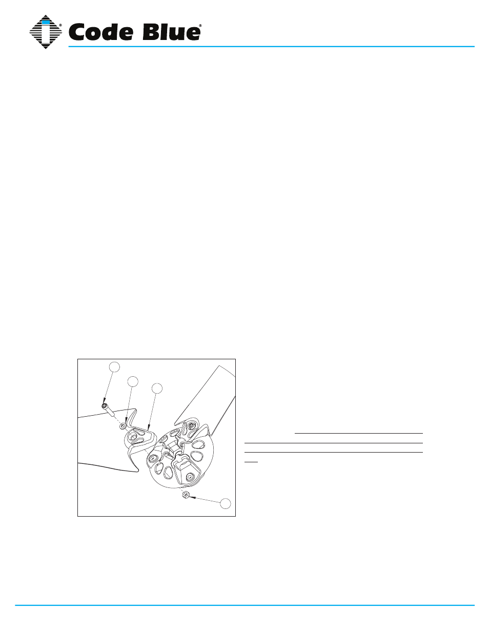
3.2.2 Start the assembly by mounting the blades (callout 1) to the blade hub as shown in
Fig.
2. Place a nylock nut (callout 4) in the hexagonal detent on the back of the blade hub
while positioning the blade on the hub. The blades must be “tilted” into position on the
hub and can only be installed in one orientation.
3.2.3 Place a washer (callout 2) on a 1/4 - 20 socket head screw (callout 3) and coat the screw
threads with Tef-Gel. Pass the screw through the base of the blade and screw it into the
nylock nut. Tighten the screw to 10 ft. lbs. (13.6 Nm).
3.2.4 Repeat for the remaining two blades.
NOTE:
Nylock nuts may only be used one time; replace after each use.
3.3
Turbine wiring – Before mounting the turbine,
mate the red, black and green connectors of the
turbine to the pre-installed wire harness in the
mounting pole.
3.4
Mount the wind generator – Route the wires
down the tower and slide the turbine yaw over the
tower top. After the yaw is completely lowered onto
the tower top, lift the yaw approximately 1/8 inch (3
mm) to 1/4 inch (6 mm) so the only contact between
the yaw and tower top is through the rubber isolation
pad. This will reduce noise and vibration transmis-
sion to the tower.
3.4.1 Once the yaw is positioned on the tower, se-
cure the yaw clamp screws using the supplied 5/32
inch hex key wrench. Torque to 5 ft. lbs. (6.8 Nm).
If blade/hub assembly is not already installed on
turbine, it may be installed now. Position the 5/8-18
nut in the hexagonal detent at the center of the hub. Coat the shaft threads and blade
hub bore with Tef-Gel and “spin” the hub completely onto the turbine alternator shaft.
Fully tighten hub to 50 ft. lbs. (67.79 Nm) by inserting a 5/16 inch hex key wrench in the
turbine alternator shaft and attempting to turn the shaft while holding the blades.
3
1
2
4
1- blades
2- washer
3- 1/4 - 20 socket head screw
4- nylock nut