Cb 1 series, Administrator guide – Code Blue CB 1-E ECONOMICAL HELP POINT User Manual
Page 45
Code Blue
•
259 Hedcor Street
•
Holland, MI 49423 USA
•
800.205.7186
•
www.codeblue.com
GU-157-E
page 45 of 71
CB 1 Series
Administrator Guide
5.1.2 Use a small Phillips screwdriver to remove the SIM cover screw that is closest to the
edge of the chassis. Loosen the second SIM screw slightly, rotate the cover 180 degrees,
and re-tighten the second SIM screw slightly to keep the SIM compartment open (See
Figure 5).
5.1.3 Orient the SIM to match the marking in the SIM
compartment (the notched part of the SIM should
be near the outer edge of the GSM unit). Insert the
SIM into its receptacle (a small needle-nosed pliers
can be helpful). Loosen the SIM cover screw slightly,
rotate the SIM cover 180 degrees to its closed posi-
tion and tighten both SIM cover screws.
5.1.4 Copy the unit’s IMEI and Serial Number on
the back for the cellular carrier before remounting
the unit to the hanger plate.
5.1.5 Attach the antenna to the GSM unit.
5.1.6 Be sure that the
VOICE/DATA switch is in the
“VOICE” position.
5.1.7 Connect power to the GSM unit.
5.1.8 Connect the RJ-11 cable to the FXS port on the rear of the GSM unit.
NOTE: The FXO port is not used; see Figure 6
5.1.9 Mount the GSM unit on the plate behind the phone with the mounting plate provided.
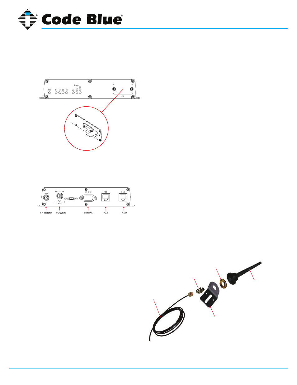
6.0 NMO MOUNT ANTENNA ASSEMBLY
6.1 Insert MTPM assembly through 5/8” mount plate hole and tighten securely with lock washer
and hex nuts provided.
6.2 Use one seal gasket for watertight seal
around 3/4” brass mount.
6.3 Attach antenna base securely to mount,
then use an N-type connector to connect
the mount to the cable.
6.4 See
Figure 7 for antenna parts assembly.
coax
MTMP mount
brass mount
mount plate
dual-band antenna
Figure 5
Figure 6