Cadac LIVE1 User Manual
Page 27
Revision L1.1 2011-12
Live1
27
Stereo returns
As well as the six mono Aux. sends, the Live1 is equipped with two stereo
returns, which are routable to the subgroups and L-R Master output in a similar
manner to the input channels. The stereo return inputs are labelled ST RT 1 L,
ST RT 1 R and ST RT 2 L, ST RT 2 R on the rear panel.
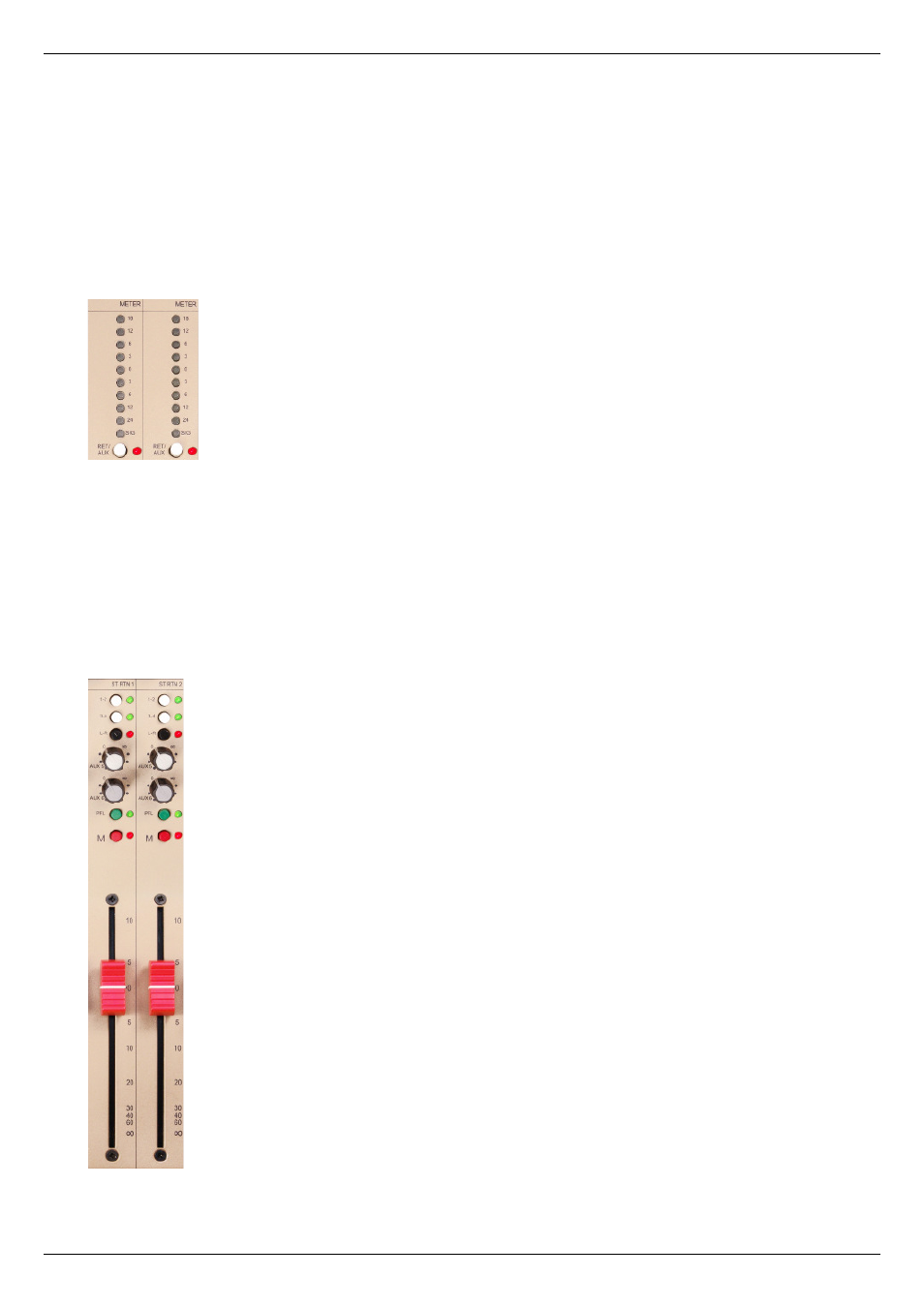
Stereo return meters:
METER
– the signal level in each stereo return (or auxiliary send – see below)
may be monitored by the 10-segment LED bargraph meter at the top of each
stereo return strip. Note the bottom LED is labelled SIG, and illuminates at a
signal level of approx. -36 dB. The LEDs are colour-coded as follows:
red:
+18 dBu
yellow: -24 dBu to +12 dBu
green: SIG
RET/AUX
– the meters may be individually switched to monitor the level of Aux.
Sends 5 to 6 instead of that of the stereo returns. (This is useful during set-up
when the console is being used for FOH work, when FX send levels may be
set and then left, the meters being returned to stereo return mode during the
show.) Pressing this button selects AUX, and an adjacent red LED illuminates to
confi rm the setting.
Note that the meters show pre-fade signals whether set to RET or AUX; i.e., in
RET mode, they indicate the stereo return level pre the return fader, and in AUX
mode, the Aux. send level pre the Aux. Master fader.
1-2
– pressing this button sends the stereo return signal to subgroups 1 and
2, left leg to 1, right leg to 2. An adjacent green LED illuminates to confi rm the
routing.
3-4
– pressing this button sends the stereo return signal to subgroups 3 and
4, left leg to 3, right leg to 4. An adjacent green LED illuminates to confi rm the
routing.
L-R
– pressing this button sends the stereo return signal to the L-R Master, left
to L, right to R. An adjacent red LED illuminates to confi rm the routing.
The routing buttons are non-interlocking; the stereo return signal may be sent to
all subgroups and/or the L-R Master simultaneously if wished.
AUX 5 and AUX 6 – the stereo returns also feature the “spin” controls described
on page 26. In this case, a mono L+R sum of the stereo return signal is sent
to Aux. send 5 and/or 6.
PFL
– pressing the PFL button routes the signal in the channel to the internal
PFL/AFL system so that it may be monitored on local speakers or headphones
connected at the MON OUT or HEADPHONES connectors respectively. The
signal continues to route normally while the PFL button is pressed. An adjacent
green LED illuminates to confi rm that PFL/AFL is active.
Monitoring of stereo returns may be either pre-fade (PFL) or after-fade (AFL);
the mode is selected globally from the Master section (see “AFL Mode on page
29). In PFL mode, the signal heard is a mono sum of the L and R legs, and