Cadac LIVE1 User Manual
Page 17
Revision L1.1 2011-12
Live1
17
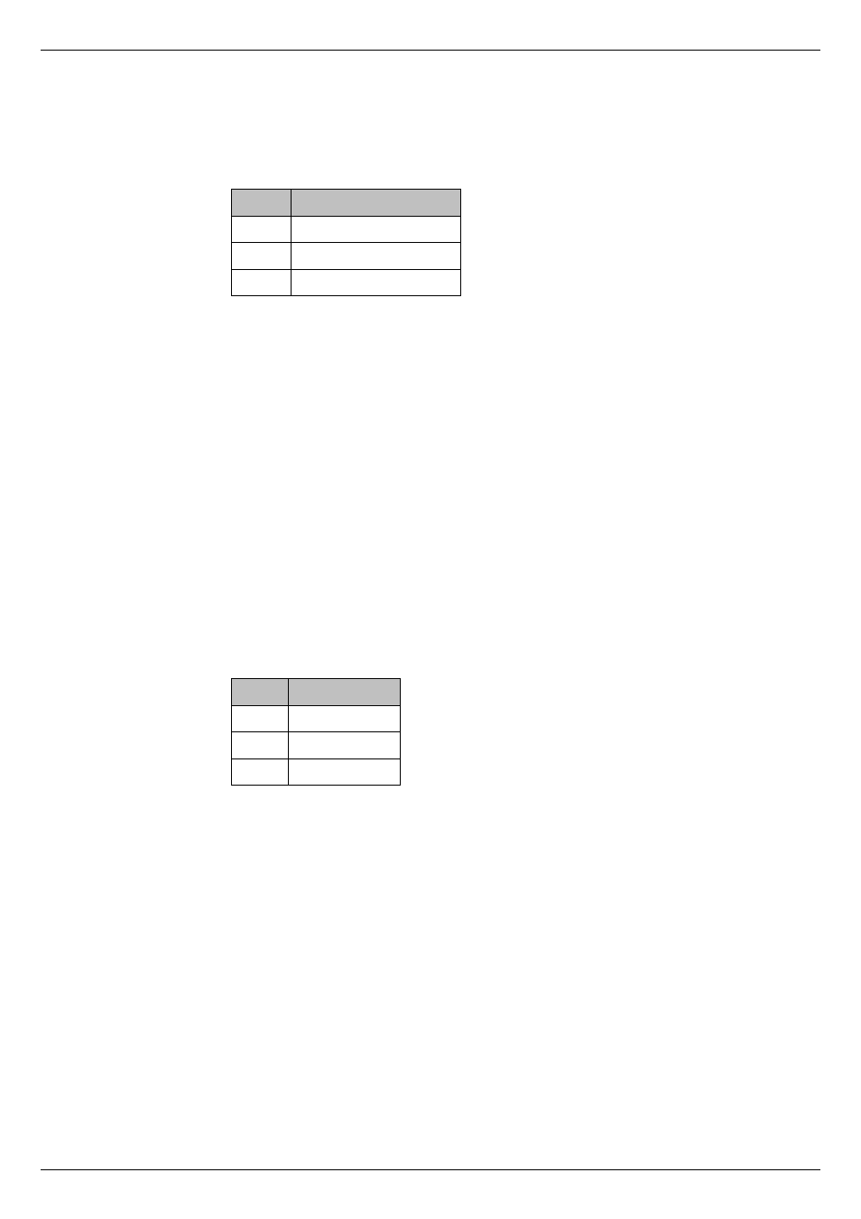
14. Headphone output – this is a single ¼” (6.35 mm) 3-pole (TRS) jack
socket carrying the same signal as at [13] above, but in unbalanced form
and at a level suitable for driving headphones of 16
impedance, or higher.
This connector should be wired as follows:
Pin
Connection
Tip
Left monitor output
Ring
Right monitor output
Sleeve
Screen (common)
15. Talkback mic – a 3-pin female XLR for connection of a talkback
microphone. Sensitivity and input impedance are the same as those for
the mic channels. Note that phantom power is permanently active at this
connector. The connector should be wired as per the table at [1] above.
16. Line in – this is an unbalanced stereo line input to the Master L/R mix.
The L and R buses are fed equally. Nominal input level is 0 dBu, input
impedance 10 k
. The connector is a 3-pole ¼” (6.35 mm) jack socket, and
should be wired as per the table at [4] above.
17. Littlites – 3-pin male XLR connector(s), providing 12 Vdc at for the
connection of Littlite
®
lamps. The current capability of each connector is
1 A. The DC supply has an internally resettable fuse. The Live1 Model
1642 is fi tted with one Littlite connector, while Models 2442 and 3242 each
have two. Littlites are directly compatible; if using other types of lights, the
connectors should be wired as follows:
PIN
Use
1
n/c
2
+12 V
3
0 V
18. Mains input – see “Powering the Live1” on page 11
It is always good operating practice to turn a mixer on BEFORE turning on
the amplifi ers, etc., to which its outputs are connected. Similarly, always
turn the amplifi ers off BEFORE turning the mixer OFF.