Cadac LIVE1 User Manual
Page 15
Revision L1.1 2011-12
Live1
15
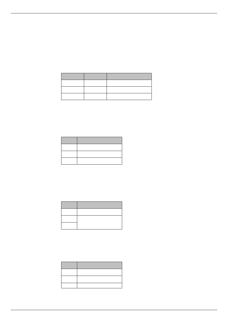
1. Mono channel inputs – 3-pin Neutrik Combo A Series connectors. These
accept either a standard 3-pin XLR male plug for microphone use, or a
1/4” (6.35 mm) 3-pole (TRS) jack plug for line level use. The inputs are
electronically balanced; the mic inputs have an impedance of 1.2 kohms
and the line inputs an impedance of approximately 10 kohms. The
sensitivity of the line input is 16 dB lower than that of the mic input, and the
maximum input level is +21 dBu. 48 V phantom power is available at the
XLR pins, via a switch on the channel strip. The connector should be wired
as follows:
XLR Pin
TRS jack
Connection
1
Sleeve
Screen
2
Tip
Signal ‘hot’ (phase)
3
Ring
Signal ‘cold’ (antiphase)
2. Mono channel inserts - ¼” (6.35 mm) 3-pole (TRS) jack sockets, for the
connection of external processing. The insert is post-EQ and pre-fade/mute.
Both send and return are unbalanced, at a nominal level of 0 dBu. The
output impedance of the send is 100
. Max. return input level is +10 dBu,
with an impedance of 10 k
. The connector should be wired as follows:
Pin
Connection
Tip
Send
Ring
Return
Sleeve
Screen (common)
3. Mono channel direct outputs – ¼” (6.35 mm) 3-pole (TRS) jack sockets.
These are unbalanced post-fade/mute outputs from each mic channel, and
can be used for multitrack recording or other purposes. The outputs have a
nominal level of 0 dBu and a max. level of +21 dBu. The connector should
be wired as follows:
Pin
Connection
Tip
Signal ‘hot’ (phase)
Ring
Screen
Sleeve
4. Stereo channel inputs - ¼” (6.35 mm) 3-pole (TRS) jack sockets. The
inputs to the four stereo line channels are balanced, with separate sockets
for left and right inputs. Nominal input level is 0 dBu into 10 k
, maximum
input level +21 dBu. The connector should be wired as follows:
Pin
Connection
Tip
Signal ‘hot’ (phase)
Ring
Signal ‘cold’ (antiphase)
Sleeve
Screen