Cadac LIVE1 User Manual
Page 22
22
Revision L1.1 2011-12
Live1
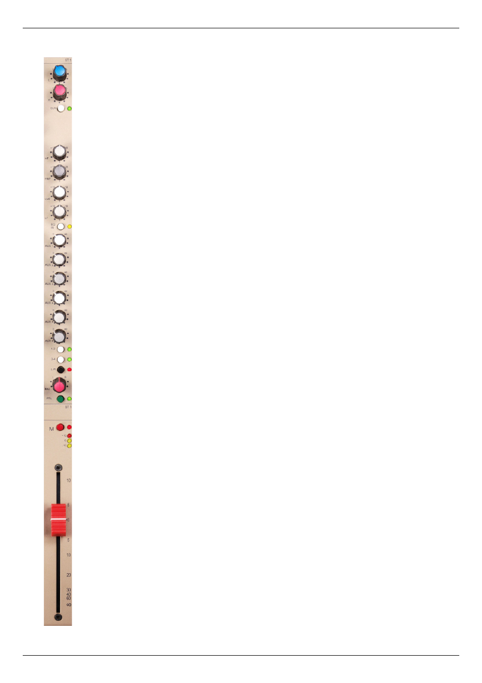
Stereo channels
Input gain:
L and R
– two controls setting input gain of left and right channels
independently; fully clockwise, the gain is 0 dB; fully anticlockwise is effectively
‘off’.
SUM
– pressing this button sums the left and right inputs (post input gain
controls), and the mix is fed equally to the left and right legs of the stereo
channel. An adjacent green LED illuminates to confi rm that the channel is
operating in mono.
Equaliser:
HF
– shelving fi lter providing 18 dB of cut or boost above 12 kHz
HMF
– bell fi lter providing 18 dB of cut or boost, centred on 4 kHz
LMF
– bell fi lter providing 18 dB of cut or boost, centred on 600 Hz
LF
– shelving fi lter providing 18 dB of cut or boost below 80 Hz
EQ IN
– when pressed, the EQ section is placed in the signal path. An adjacent
yellow LED illuminates to confi rm this.
Auxiliary sends:
The six aux sends are identical. All sends are mono, and in the stereo channels,
each receives an L+R mix of the left and right legs. Each has its own send level
control. With the control fully anticlockwise, the send is off. The sends may
be selected as pre- or post-fade in pairs – i.e., 1 & 2, 3 & 4 and 5 & 6 – from
the master section (see “Master Aux Pre/Post” on page 29). Note that the
channel MUTE button mutes both pre-fade and post-fade sends.
Routing & panning:
The routing buttons are non-interlocking; the channel signal may be sent to all
subgroups and/or the master output simultaneously if wished.
1-2
– pressing this button sends the post-fade signal to subgroups 1 and 2, via
the PAN control. An adjacent green LED illuminates to confi rm the routing.
3-4
– pressing this button sends the post-fade signal to subgroups 3 and 4, via
the PAN control. An adjacent green LED illuminates to confi rm the routing.
L-R
– pressing this button sends the post-fade signal to the master L and R
outputs, via the PAN control. An adjacent red
LED illuminates to confi rm the
routing.
BAL
– allows adjustment of the image of the stereo signal. The control is
calibrated L - 0 - R; in the L and R positions, a level offset of 4.5 dB is applied
to the two legs. In the 0 position, the stereo image of the original input signal is
maintained.
PFL
– pressing the PFL button routes the signal in the channel to the internal
PFL/AFL system so that it may be monitored on local speakers or headphones
connected at the MON OUT or HEADPHONES connectors respectively. The
signal continues to route normally while the PFL button is pressed. An adjacent
green LED illuminates to confi rm that PFL/AFL is active.