2 starting up, 1 check properties, 2 rated pressure test inspection – Bronkhorst LIQUI-FLOW mini (from 01-07-2013) User Manual
Page 7: 3 check piping, 4 install system, Starting up, Check properties, Rated pressure test inspection, Check piping, Install system
LIQUI-FLOW™ mini
© 2013 Bronkhorst High-Tech BV
Bronkhorst High-Tech BV
7
2
Starting up
2.1
Check properties
1. Check LIQUI-FLOW
TM
mini properties
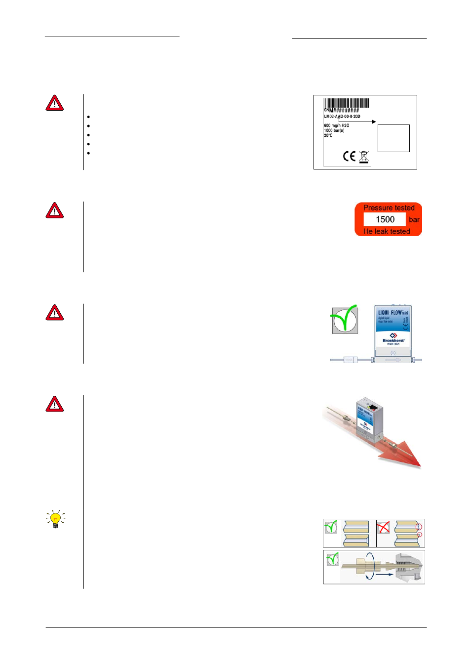
Before installing it is important to read the attached label and check:
Flow rate
Pressure
Fluid to be measured
Input and output signals
Temperature
Output
A – 0…5 Vdc
B – 0…10 Vdc
F – 0…20 mA
G – 4…20 mA
2.2
Rated pressure test inspection
Each LIQUI-FLOW
TM
mini instrument is pressure tested to at least 1.5 times
the working pressure of the process conditions stipulated by the customer.
The tested pressure is stated on the instrument with a red-coloured sticker.
Before installation, make sure that the test pressure is in accordance with
normal safety factors for your application. If there is no Pressure Testing
Sticker on the device or if the test pressure is incorrect, the instrument
should not be mounted in the process line and be returned to the factory.
2.3
Check piping
For reliable measurement always make sure that the fluid stream is clean.
Use filters to ensure a particle-free liquid stream. Recommended pore-size:
2 µm. If back flow can occur, a downstream filter is recommended too. Be
aware of the pressure drop caused by using filters.
2.4
Install system
For LIQUI-FLOW
TM
mini the upright position is preferred. When using a
LIQUI-FLOW
TM
mini instrument in up- or downward position make sure to
“zero” the instrument prior to use (see section 2.10). Avoid installation in
close proximity of mechanic vibration and/or heat sources. The housing of
the instrument is according to class IP40, which means that the instrument is
suitable for indoor (dry) applications, like laboratories or well protected
(OEM) housings.
Install the LIQUI-FLOW
TM
mini instrument in the line, in accordance with the
direction of the FLOW arrow. The arrow for flow direction is indicated on the
body of the instrument. If applicable follow the guidelines of the supplier of
the fittings. Special types of fittings are available on request.
10-32 UNF fittings
Tighten the 10-32 UNF fittings according to the instructions of the
supplier of the fittings.
Only use 1/16” tubing with a straight and clean cut without burrs to
ensure leak tightness. Preferably deburr the tubing prior to
installation. A new ferrule connection must be made for each new
adapter to ensure leak-tightness and minimum dead volume, due to
variances in the adapter dimensions.