3 basic operation, 1 general, 2 analog operation – Bronkhorst LIQUI-FLOW mini (from 01-07-2013) User Manual
Page 12: Basic operation, General, Analog operation, 3basic operation
LIQUI-FLOW™ mini
9.17.065
Bronkhorst High-Tech BV
12
3
Basic operation
3.1
General
A LIQUI-FLOW
TM
mini instrument must be powered with +15…+24 Vdc according to the applicable hook-up diagram, supplied with
the instrument. The instrument can be operated by means of:
Analog interface: 0…5 Vdc; 0…10 Vdc; 0…20 mA or 4…20 mA
Digital RS232 interface (FLOW-BUS (Propar) protocol)
Digital RS485 interface (Modbus RTU, Modbus ASCII or FLOW-BUS protocols)
By default the instrument is set as specified. The table below lists the supported interfaces.
Analog interface
Digital RS232 interface
Digital RS485 interface
LM02
0…5 Vdc; 0…10 Vdc;
0…20 mA; 4…20 mA
(software selectable)
FLOW-BUS (Propar) protocol on 9600,
19200, 38400, 57600 or 115200 Baud
(software selectable)
Modbus RTU and Modbus ASCII protocols
on 9600, 19200, 38400, 56000, 57600 or
115200 Baud; FLOW-BUS protocol on
187500 or 400000 Baud (software
selectable)
3.2
Analog operation
At analog operation the measured value (analog output) is available at pin 2.
The selected analog interface (0…5 Vdc; 0…10 Vdc; 0…20 mA or 4…20 mA) can be found in the model key of the instrument.
See section 2.15.
When operating the instrument through the analog interface it is possible to connect the instrument simultaneously
to RS232 for reading/changing parameters (e.g. settings or fluid selection).
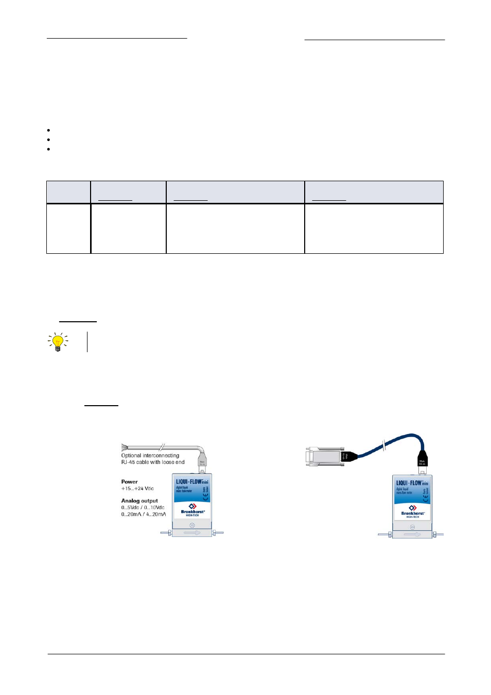
Hook-up
For analog operation either an RJ-45 loose-end cable or an RJ-45 to 9-pin sub-D converter may be used to connect the required
signals.
Refer to the section 2.7 or use an RJ-45 loose-end cable
(7.03.419) to connect the required signals.
When using a Bronkhorst readout unit use only an RJ-45
cable (7.03.236) in combination with the RJ-45 to 9-pin
sub-D converter (7.03.376). With these items the pin
configuration is unchanged.