11 zeroing, 12 calibration, 13 supply pressure – Bronkhorst LIQUI-FLOW mini (from 01-07-2013) User Manual
Page 10: 14 measuring principle, Zeroing, Calibration, Supply pressure, Measuring principle
LIQUI-FLOW™ mini
9.17.065
Bronkhorst High-Tech BV
10
may either be on or off.
2.11 Zeroing
The zero point of each instrument is factory adjusted. If required the zero point can be re-adjusted over RS232 or by
means of using the micro-switch. Procedure for zeroing by-micro switch:
Warm-up, pressure up the system and fill the instrument according to the process conditions.
Make sure no flow is going through the instrument by closing valves near the instrument.
Press micro-switch and hold it. After a short time the red LED will go ON and OFF, then the green LED will go ON.
At that moment release the micro-switch.
The zeroing procedure will start at that moment and the green LED will blink fast. The zeroing procedure waits for
a stable signal and saves the zero. If the signal is not stable, zeroing will take long and the nearest point to zero is
accepted. The procedure will take approximately 10 seconds.
When the indication is showing 0% signal and the green indication LED is burning continuously again, the zeroing
action was successful.
2.12 Calibration
Each LIQUI-FLOW
TM
mini instrument is factory calibrated. Bronkhorst High-Tech B.V. certifies that all instruments
meet the rated accuracy. Calibration is performed using measurement standards traceable to the standards of the
Dutch Metrology Institute (VSL). Calibration certificates are included in the shipment. When operated properly
(clean fluid, no pressure shocks, no vibrations, no thermal shocks, etc.), regular maintenance is not required.
However, periodical inspection, recalibration or verification of the accuracy may be subject to individual
requirements of the end-user.
2.13 Supply pressure
It is recommended to turn on power before applying pressure on the instrument and to switch off power after
removing pressure.
Turn on fluid supply gently. Avoid pressure shocks and bring the instrument gradually up to the level of the actual
operating conditions. Also switch off fluid supply gently.
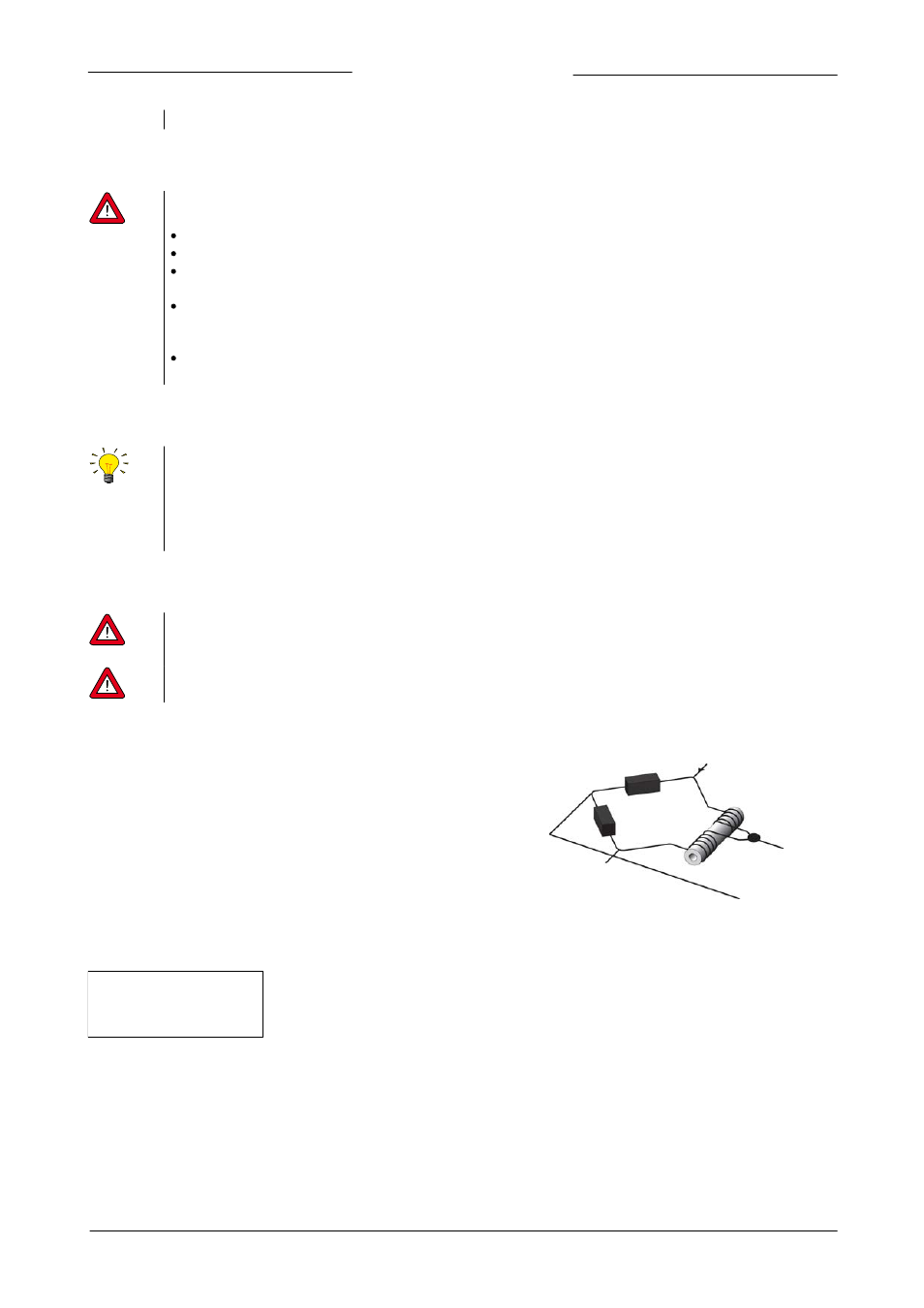
2.14 Measuring principle
The liquid flow sensor operates on a principle of heat transfer by sensing the
temperature difference along a heated section of a capillary tube. The
temperature difference sensed by the upstream and downstream
temperature sensors on the capillary depends on the amount of heat
absorbed by the fluid flow. The temperature sensors are part of a bridge
circuit, as seen in the figure. The measured imbalance of the bridge, caused by
the flow in the capillary is linearised to the mass flow rate and amplified to the
desired signal level.
Thermal sensor in a bridge configuration
The transfer function between mass flow and sensor signal can be described by the equation:
V
signal
= K . c
p
. Ö
m
with:
V
signal
= sensor signal
K
= constant factor
c
p
= specific heat of the fluid
Ö
m
= mass flow
From this formula it can be concluded that for each different fluid (with heat capacity c
p
) a certain sensor signal represents a
different mass flow. Using accurate fluid data and a conversion factor it is possible to predict the mass flows for liquids other than
water.