4 changing slave address, baud rate and parity, Changing slave address, baud rate and parity – Bronkhorst LIQUI-FLOW mini (from 01-07-2013) User Manual
Page 26
LIQUI-FLOW™ mini
9.17.065
Bronkhorst High-Tech BV
26
4.2.4
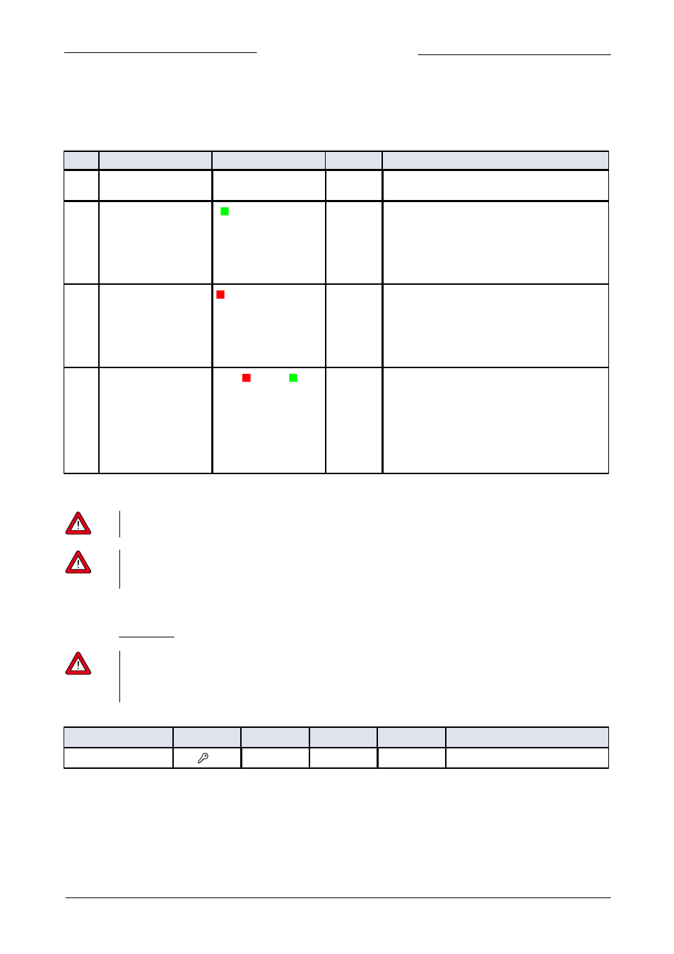
Changing slave address, baud rate and parity
Changing node address or baud rate by micro-switch operation
Press the micro-switch 5x briefly with intervals of max. 1 second in normal running/operation mode. Within the timeout period of
60 seconds it is possible to start changing the node address and baud rate of the instrument.
Step
Action
Indication
Time
Handling
1
Start
Press the switch 5x briefly with intervals of max. 1
second in normal running/operation mode.
2
Set tens of bus address
Green LED flashes
0.1 sec on, 0.1 sec off
count flashes
start when switch
is pressed:
0.5 sec on, 0.5 sec off
timeout:
60 sec
Press switch and count green flashes for tens of
bus address.
Release when wanted amount has been count.
Counts up to max. 12 and than starts at 0 again.
When counting fails, keep switch pressed and
restart counting for next attempt.
3
Set units of bus address
red LED flashes
0.1 sec on, 0.1 sec off
count flashes
start when switch
is pressed:
0.5 sec on, 0.5 sec off
timeout:
60 sec
Press switch and count red flashes for units of bus
address.
Release when wanted amount has been count.
Counts up to max. 9 and than starts at 0 again.
When counting failed, keep switch pressed and
restart counting for next attempt.
4
Set baud rate of field
bus communication.
1 = 9600 Baud
2 = 19200 Baud
3 = 38400 Baud
4 = 56000 Baud
5 = 57600 Baud
6 = 115200 Baud
both red and
green LEDs flashes
0.1 sec on, 0.1 sec off
count flashes
start when switch
is pressed:
0.5 sec on, 0.5 sec off
timeout:
60 sec
Press switch and count red and green flashes for
baud rate setting.
Release when wanted amount has been count.
Counts up to max. 5 and than starts at 0 again.
When counting failed, keep switch pressed and
restart counting for next attempt.
Note: selection of 0 means: No change
Instrument returns to normal running / operation mode. Changes are valid when they are made within the time-out times.
Value zero will be indicated by a period of 1 sec off (0.5 sec off + 0,5 sec off).
When value zero is wanted, press switch shortly and release it again within 1 sec.
Before each action of flash-counting, the LEDs to be used for counting will flash in a high frequency.
(Pattern: 0.1 sec on, 0.1 sec off). As soon as the switch is pressed-down, this LED (or both LEDs) will be off and the
counting sequence will start.
Changing node address, baud rate or parity in 'Configuration Mode' or in normal mode
The procedure for changing the baud rate, node address or parity for a FLOW-BUS or Modbus configuration over RS485 is
described in Section 3.5.3. In the list below the selectable bus parameters with corresponding values are presented.
When changing any of the parameters below in normal running/operation mode the communication with the
instrument may be lost. After a restart the instrument is available for communication on the newly selected
parameters. When in doubt activate the 'Configuration Mode' (38k4 and RS232 FLOW-BUS (Propar)) using the
micro-switch.
Fieldbus 2 selection
Type
Access
Range
FlowDDE
FLOW-BUS
Modbus
Unsigned char
RW
0…3
308
124/8
0xFC40/64577
This parameter sets the fieldbus type. Parameter value 0 = FLOW-BUS, 1 = Modbus RTU, 2 = Propar, 3 = Modbus ASCII