2 led functions, 4 basic rs232 operation, 1 hook-up – Bronkhorst LIQUI-FLOW mini (from 01-07-2013) User Manual
Page 14: Led functions, Basic rs232 operation, Hook-up, Section 3.4, Section 3.3.2
LIQUI-FLOW™ mini
9.17.065
Bronkhorst High-Tech BV
14
LEDs
Time
Pushed
Indication
Green
Red
Off
Off
0 – 4 sec.
No action. Pressing a switch shortly by accident will not start any unwanted
reaction of the instrument.
Off
Normal
flash
0,2 sec on,
0,2 sec off
4 – 8 sec.
Restore factory settings
All parameter settings (except field bus settings) will be restored to situation of
final test at BHT production.
Normal
flash
0,2 sec on,
0,2 sec off
On
8 – 12 sec.
For FLOW-BUS only: install a free node-address on FLOW-BUS.
Normal
flash
0,2 sec on,
0,2 sec off
Normal
flash
0,2 sec on,
0,2 sec off
12 – 16 sec
Activate 'Configuration Mode'. The baud rate and bus type are set to 38k4 and
RS232 FLOW-BUS (Propar). The 'Configuration Mode' is recognized by the
green LED blinking 2 sec on, 0,1 sec off. The 'Configuration Mode' is
deactivated only after applying this micro-switch action again.
LED indications using micro-switch at power-up situation of an instrument
3.3.2
LED functions
The LEDs on top of the instrument can also be used for manual operation of some options. The green LED will indicate in what
mode the instrument is active. The red LED will indicate error/warning situations.
i
www
For details see “Manual interface: micro-switch and LEDs” in Operation Instructions Digital Instruments:
(document nr. 9.17.023, Chapter 11)
3.4
Basic RS232 operation
Digital operation adds a lot of extra features (compared to analog operation) to the instruments, such as:
Up to eight selectable fluids (if installed)
Direct reading at readout/control module or host computer
Testing and self diagnosis
Identification (serial number, model number, device type, user tag)
Adjustable minimal and maximal alarm limits
(Batch) counter
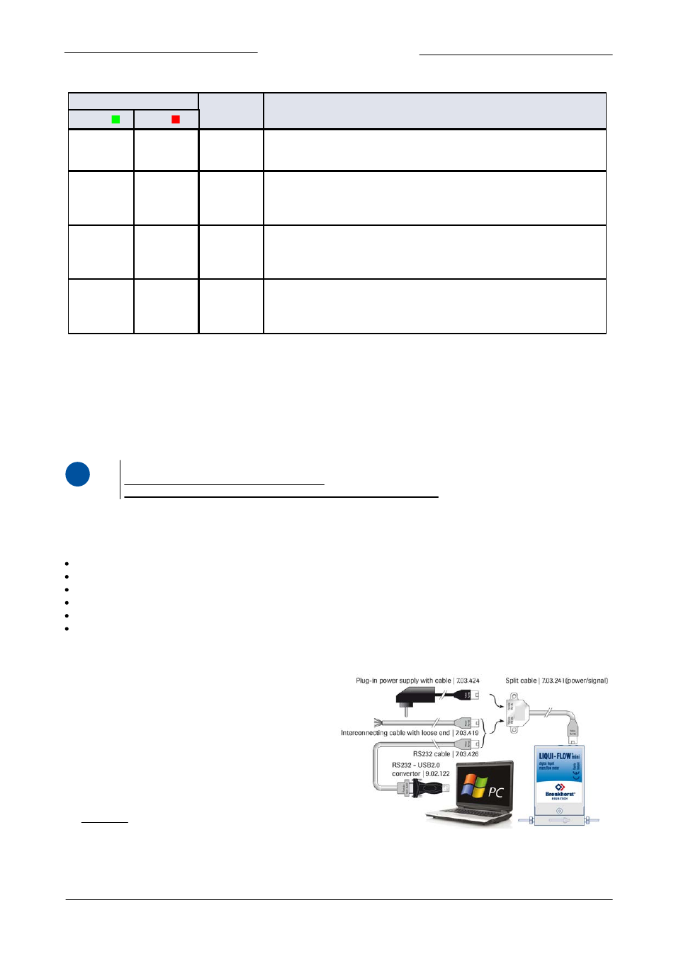
3.4.1
Hook-up
Connecting a LIQUI-FLOW
TM
mini instrument to a COM port of a
pc requires a special cable (7.03.426) which changes the
appropriate pin configuration. Optionally use an RS232 to USB2.0
converter (9.02.122) to connect to a USB port. Use the split cable
(Y-adapter 7.03.241) in combination with the Plug-in Power
Supply (7.03.424) for powering the instrument.
Instead of using a COM or USB port, it is also possible to connect
the RS232 pinning manually using the loose-end cable (7.03.419),
typically for connection to PLC or micro controller devices.
See section 2.7 for the Hook-up diagram.