4 display filter, 5 alarm / status parameters, 6 counter parameters – Bronkhorst LIQUI-FLOW mini (from 01-07-2013) User Manual
Page 23: Display filter, Alarm / status parameters, Counter parameters
LIQUI-FLOW™ mini
© 2013 Bronkhorst High-Tech BV
Bronkhorst High-Tech BV
23
4.1.4
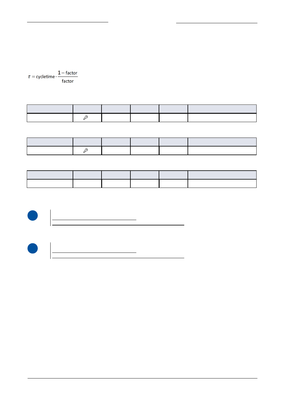
Display filter
The output signal of a LIQUI-FLOW
TM
mini instrument (measured value) is filtered. The filter has dynamic behaviour: when a change
in sensor signal is detected, the measured value will be less filtered than when the sensor signal is constant and stable. There are
two filter constants: Static Display Factor and Dynamic Display Factor. These two factors can be transformed into time constants
using the following formula:
The measured value is filtered with a first order low pass filter with a filter time constant between the two ô values.
Dynamic Display Factor
Type
Access
Range
FlowDDE
FLOW-BUS
Modbus
Float
RW
0…1.0
56
117/1
0xF508…0xF509/62729…62730
This value should not be changed.
Static Display Factor
Type
Access
Range
FlowDDE
FLOW-BUS
Modbus
Float
RW
0…1.0
57
117/2
0xF510…0xF511/62737…62738
This value should not be changed.
CycleTime
Type
Access
Range
FlowDDE
FLOW-BUS
Modbus
Unsigned char
R
0…255
52
114/12
0x0E4C/3661
Note: The unit of parameter CycleTime is 10 ms. Example: value 0.2 means 2 ms
4.1.5
Alarm / Status parameters
i
www
See document nr. 9.17.023: Operational instructions for digital instruments, chapter 6.
4.1.6
Counter parameters
i
www
See document nr. 9.17.023: Operational instructions for digital instruments, chapter 7.