2 led functions – Bronkhorst IQ+FLOW (till 01-07-2013) User Manual
Page 13
9.17.045
page 13
3.3.2 LED functions
The LEDs on top of the instrument can also be used for manual operation of some options. The green LED will indicate
in what mode the instrument is active. The red LED will indicate error/warning situations.
For details see “Manual interface: micro-switch and LEDs ” in Operation Instructions Digital
Instruments (document nr. 9.17.023, Chapter 11)
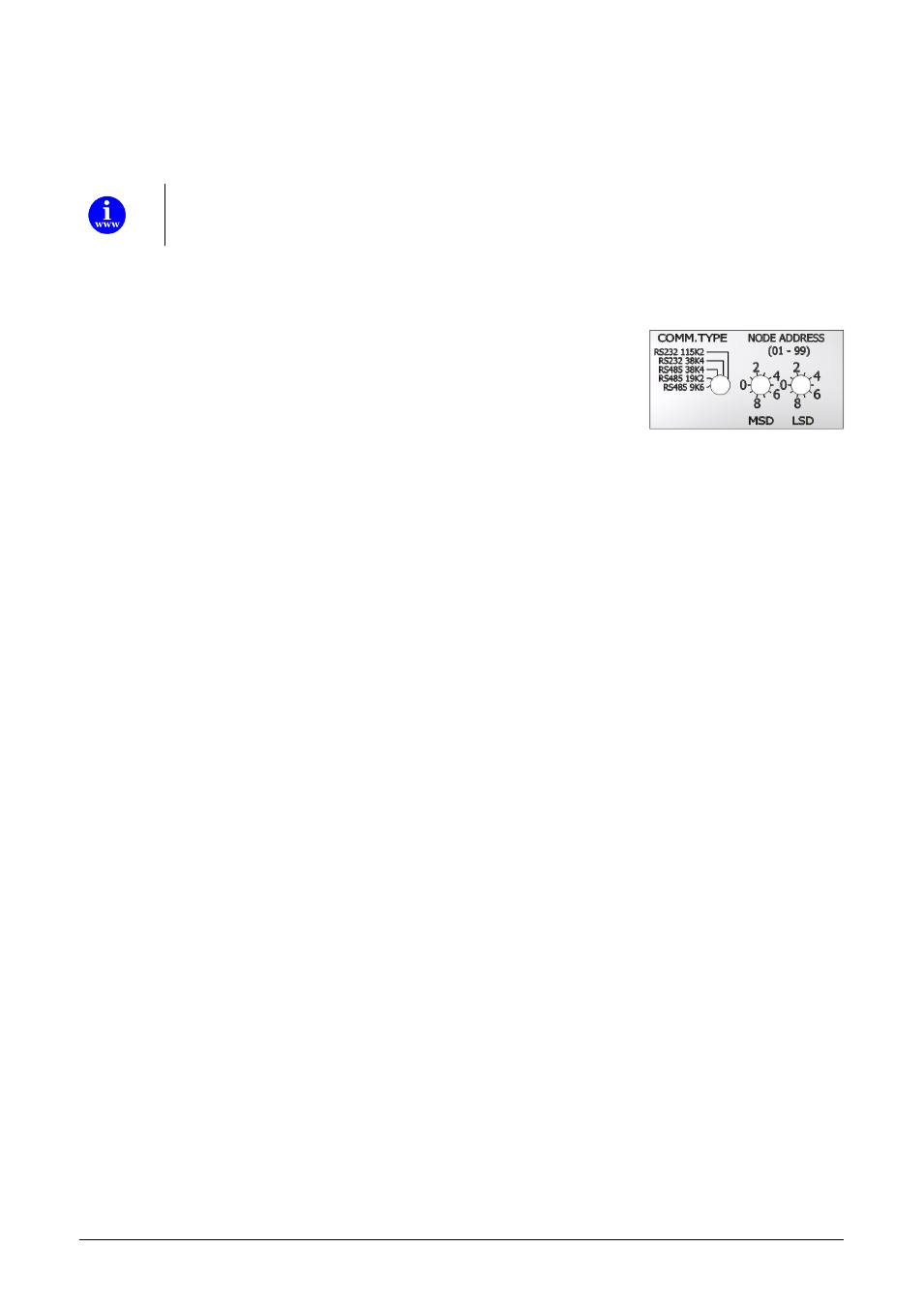
3.3.3 Rotary switch operation (multi-channel versions only)
The IQ+FLOW® multi-channel instruments are equipped with rotary switches for
selection of communication type, Baud rate and node address.
Communication type switch
With the ‘COMM. TYPE’ switch the following communication types can be selected:
0.
RS485 9k6: Modbus RTU protocol with Baud rate 9600, EVEN parity
1.
RS485 19k2: Modbus RTU protocol with Baud rate 19200, EVEN parity
2.
RS485 38k4: Modbus RTU protocol with Baud rate 38400, EVEN partiy
3.
RS232 38k4: FLOW-BUS protocol with Baud rate 38400
4.
RS232 115k2: FLOW-BUS protocol with Baud rate 115200
Node address switches
With the two ‘NODE ADDRESS’ switches the node address of the instrument channels can be selected. The ‘MSD’
(Most Significant Digit) sets the first digit (tens), the ‘LSD’ (Least Significant Digit) sets the second digit (units). The
node address of channel 1 is set with the switches, the channels 2 and 3 receive ‘node address’ + 1 and ‘node address’
+ 2 respectively (e.g. MSD = 1 and LSD = 9 selects node 19 for channel 1, but also node 20 and 21 for channels 2 and 3).