Measure control – Bronkhorst Multibus User Manual
Page 9
BRONKHORST
®
Page 9
Operational instructions for digital multibus instruments
9.17.023
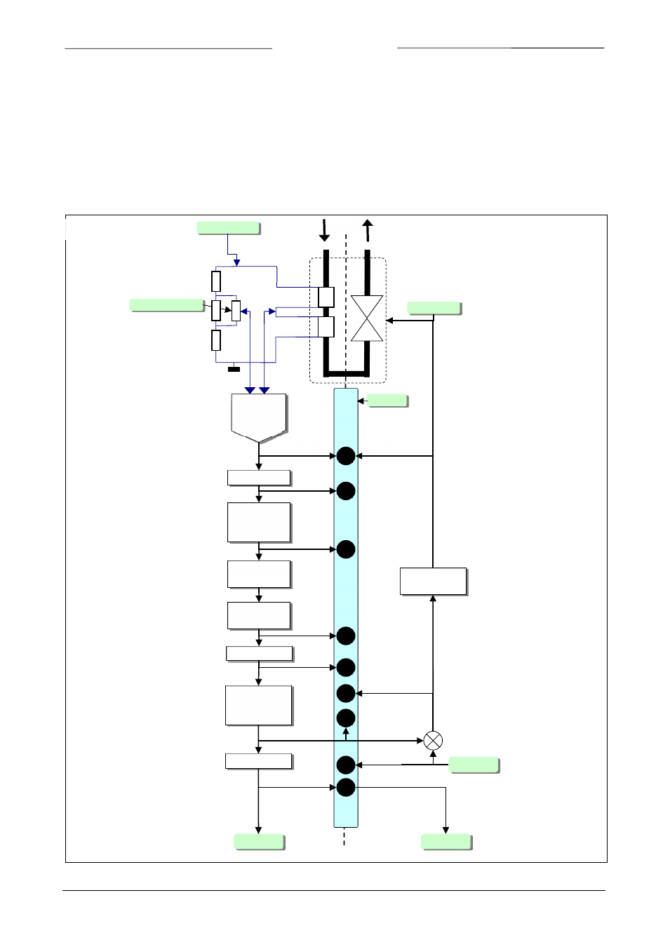
2.3 M
EASURE AND CONTROL FUNCTIONAL BLOCK DIAGRAM
The main part of a digital instrument is the measuring stage. The base is a highly accurate Analog to Digital converter.
The measuring signal is than processed trough a couple of stages as shown below. In general the path is: ADC scaling,
filtering, linearization (look-up or polynomial), Differentiation (gas flow sensors only), display filtering. In case of a
control system this signal is used to control a valve. The control loop consists of an enhanced PID controller (See the
chapter “Control parameters”).
Digital mass-flow measure / controller functional block diagram
ADC
converter
Bridge potmeter
ADC scaling
3
Bridge current
Exponential
smoothing
filter
4
Lookup table
linearization
Polynomial
linearization
Differentiator
5
6
7
8
Differentiator
filter
(MBC-II only)
1
Setpoint
0
Display filter
fmeasure
Measure
PID
controller
2
VALVE
SENSOR
FLOW
MEASURE
CONTROL
Monitor
Valve Out
MBC3
MBC-II