2 digital instrument, Digital signal processing – Bronkhorst Multibus User Manual
Page 7
BRONKHORST
®
Page 7
Operational instructions for digital multibus instruments
9.17.023
2 DIGITAL INSTRUMENT
2.1 G
ENERAL
A digital instrument of Bronkhorst is a Mass Flow or Pressure Meter / Controller which is equipped with a digital
electronic Multibus PC board. These electronics consist of a micro-controller with peripheral circuitry for measuring,
controlling and communication. The flow/pressure signal is measured and digitized directly at the sensor and
processed by means of the internal software (firmware). Measured and processed values can be output through the
analog interface and through the digital communication line RS232 (and optional field bus interface). For controllers
the setting for the actuator is calculated by the firmware. Setpoint can be given through the integrated analog
interface or through the digital communication line. Digital instruments have many parameters for settings for signal
processing, controlling and many extra features and therefore they have a wide range in use. Reading and changing of
these settings is possible through field bus or RS232, except for measured value, setpoint and valve output, which is
also possible through the analog interface. (Depending on parameter setting) See operating instructions of Readout
and Control module or PC-program how to read/change parameter values of digital instruments.
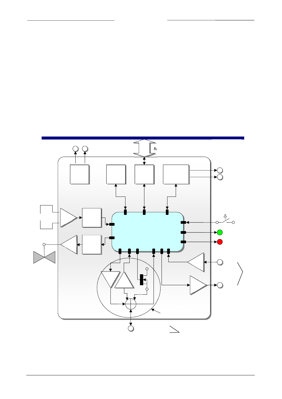
2.2 B
ASIC DIAGRAM
Measure
FIELD BUS
Interface
PID
controller
Read and write parameters
FIELD BUS
Data
Memory
Sensor
Valve
Digital Signal
Processing
LED Green
LED Red
Micro-
switch
PWM
AD
DA
AD
Analog
Input
0…5V
0…10V
0…20mA
4…20mA
Analog
Output
Supply
Voltage
1 Analog Output
DA
AD
2 Analog Input
3 Digital Output
4 Digital Input
RS232/
RS485
Interface
1
2
3
4
MBC3 type only
0…5V
0…10V
0…20mA
4…20mA
RS232/
(RS485)
15…24Vdc