11 manual interface: micro-switch and led’s – Bronkhorst Multibus User Manual
Page 41
BRONKHORST
®
Page 41
Operational instructions for digital multibus instruments
9.17.023
11 MANUAL INTERFACE: MICRO-SWITCH AND LED’S
11.1 G
ENERAL
The micro-switch on top of the digital instrument can be used to start a certain function at the instrument. When the
switch is pressed down, both LED’s will start indicating different patterns in a loop. The switch has to be pressed down
until the 2 LED’s are indicating the right pattern. Then the switch has to be released and the choice has been made.
Normally (when the switch is not pressed) the green and red LED are used for mode indication on digital instruments
(FLOW-BUS / PROFIBUS-DP / DeviceNet / Modbus/EtherCAT).
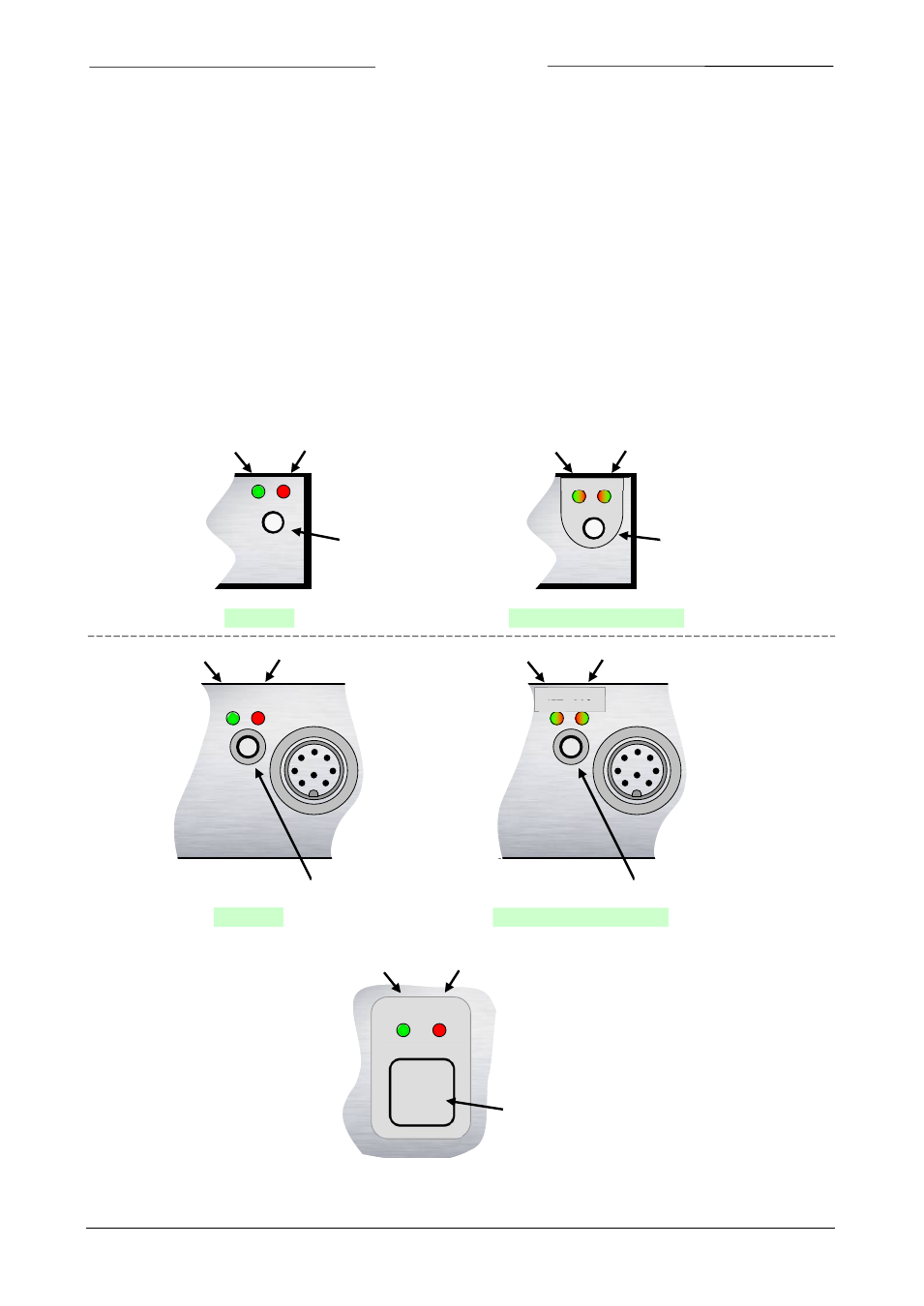
11.1.1 LED and switch locations
GREEN
RED
MICRO-
SWITCH
GREEN/RED
GREEN/RED
MICRO-
SWITCH
Normal
DeviceNet (MBC3)
GREEN
RED
MICRO-
SWITCH
Normal
GREEN/RED GREEN/RED
MICRO-
SWITCH
DeviceNet (MBC3)
NET MOD
STATUS
NET MOD
STATUS
LAB casing
Industrial
casing
#
GREEN
RED
SWITCH