Bronkhorst Multibus User Manual
Page 37
BRONKHORST
®
Page 37
Operational instructions for digital multibus instruments
9.17.023
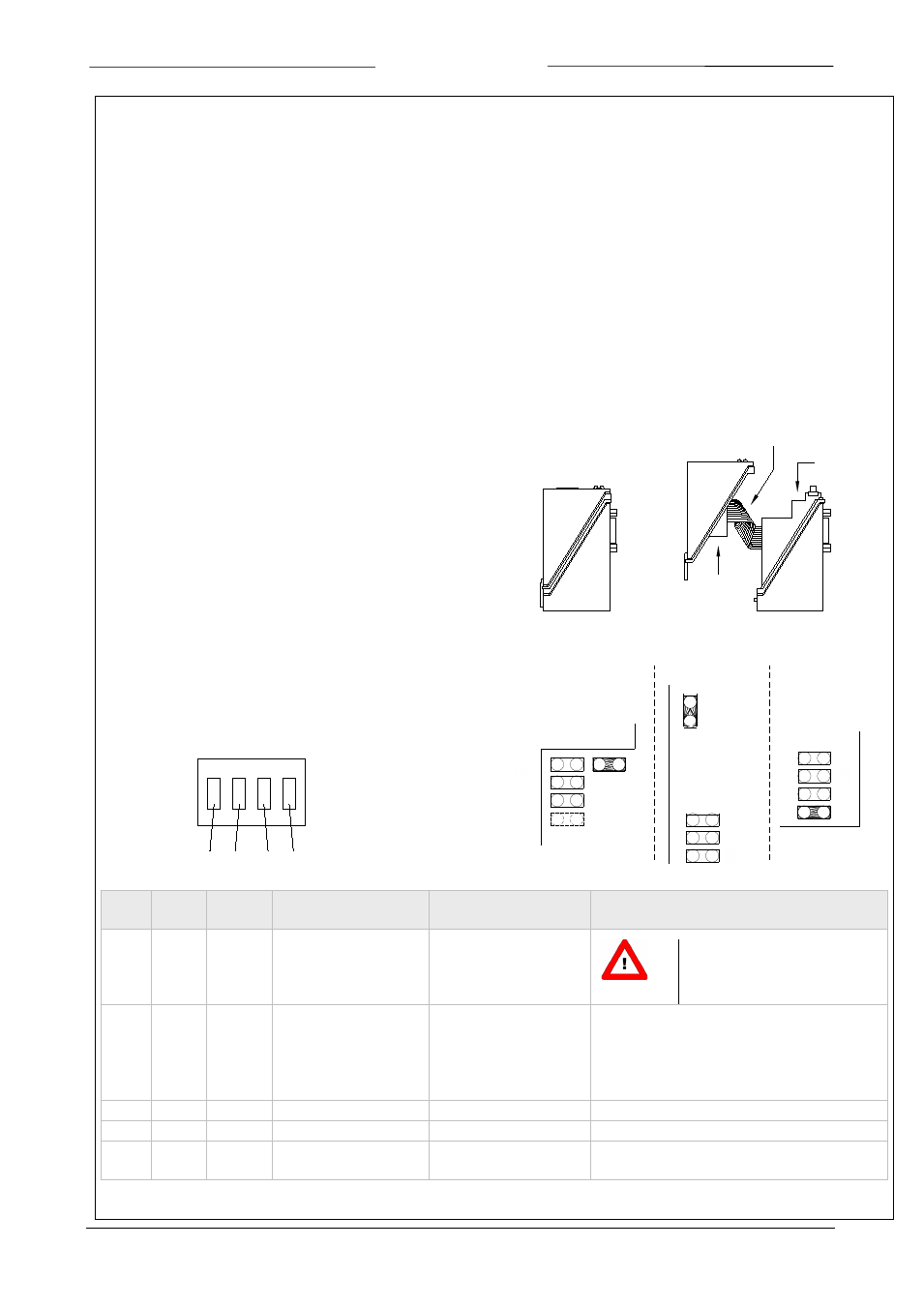
Flatconductor
cable
main PC board
fieldbus
interface
1
2
3
4
S1
S2
S3
S4
on
off
9.4.1 Examples of using parameter IOstatus
•
When the analog jumper is set the value of parameter 86 will read: 1+2+4+8+64 = 79
•
To disable the micro switch bit 3 must be false, value of parameter 86 must be set to.: 1+2+4 = 7
•
To disable the analog jumper bit 2 must be false, value of parameter 86 must be set to: 1+2+8= 11
Bit 2 = 0 (don't read ‘analog jumper’)
At power-on of an instrument the jumper will not be read.
The control mode will remain on the value as it was before power-off.
Only when the control mode before power-off is set to the value 5, 9, 18 or 19 the control mode will switch to 0 (digital).
Bit 2 = 1 (read ‘analog jumper’)
At power-on of an instrument the jumper will be read.
Only when the control mode before power-off is set to the value 0, 1, 5, 9, 18 or 19 the control mode will switch to:
-
0 (digital) when jumper 2 is not placed.
-
1 (analog input) when jumper 2 is placed.
9.4.2 Examples of using real jumpers (MBC-I and MBC-II
type)
In normal operation it is not necessary to change the jumper
setting. If it cannot be avoided, the jumpers can be reached by
removing the uppercase of the housing. Opening the uppercase
should be done with great care, because the connection of the
field bus and main p.c. board is accomplished by a small flat
conductor cable.
Each jumper or switch can be used to make a certain setting
by placing a link between a set of pins or by switching one of
the DIP-switches as shown below:
with DIP switch
Switch Jumper IOstatus
bit
When placed
(on)
When not placed
(off)
Remarks
S2
J1
5
Default settings from
EPROM loaded at
power-up
Settings loaded from
non-volatile memory at
power-up
If S2 is placed all settings are
erased, including factory
calibration.
S3
J2
6
Analog input used as
standard setpoint for
controller at power-up
Digital (bus) input used
as standard setpoint for
controller at power-up
Setting depends on how instrument was
ordered. Setting can be changed during
normal operation using parameter “Control
Mode”. At next power-up however, controller
will read jumper first for setpoint source.
S4
J3
4
reserved
-
J4
reserved
Not always present
S1
J5
Normal RS232
communication
Instrument in FLASH
mode
(J4)
J5
J1
J3
J2
J5
CORI-FLOW
J2
J1
J3
MBC-II
J1
J2
J3
J5
L30
digital
With Jumper