14 v, 15 t, 16 a – Bronkhorst Multibus User Manual
Page 20: 17 s, 18 c, 19 c
BRONKHORST
®
Page 20
Operational instructions for digital multibus instruments
9.17.023
4.14 V
ALVE OUTPUT
unsigned long
0…16777215
RW
Y
55
114/1
This parameter is the signal coming out of the controller, going to the DAC for driving the valve. 0...16777215
corresponds with approximately 0...300mAdc. Maximum output voltage is the supply voltage and therefore in practice
300 mAdc may not be reached.
4.15 T
EMPERATURE
float
-250…500
RW
N
142
33/7
In MBC3 type of instruments the temperature surrounding the sensor is shown.
For (mini) CORI-FLOW type of instruments this parameter shows the temperature of the tubes.
It is not used in other instruments.
4.16 A
CTUAL DENSITY
float
-3.40282E+38 …
3.40282E+38
R
N
270
116/15
This parameter shows the Actual Density measured by the (mini) CORI-FLOW. It is not used in other instruments.
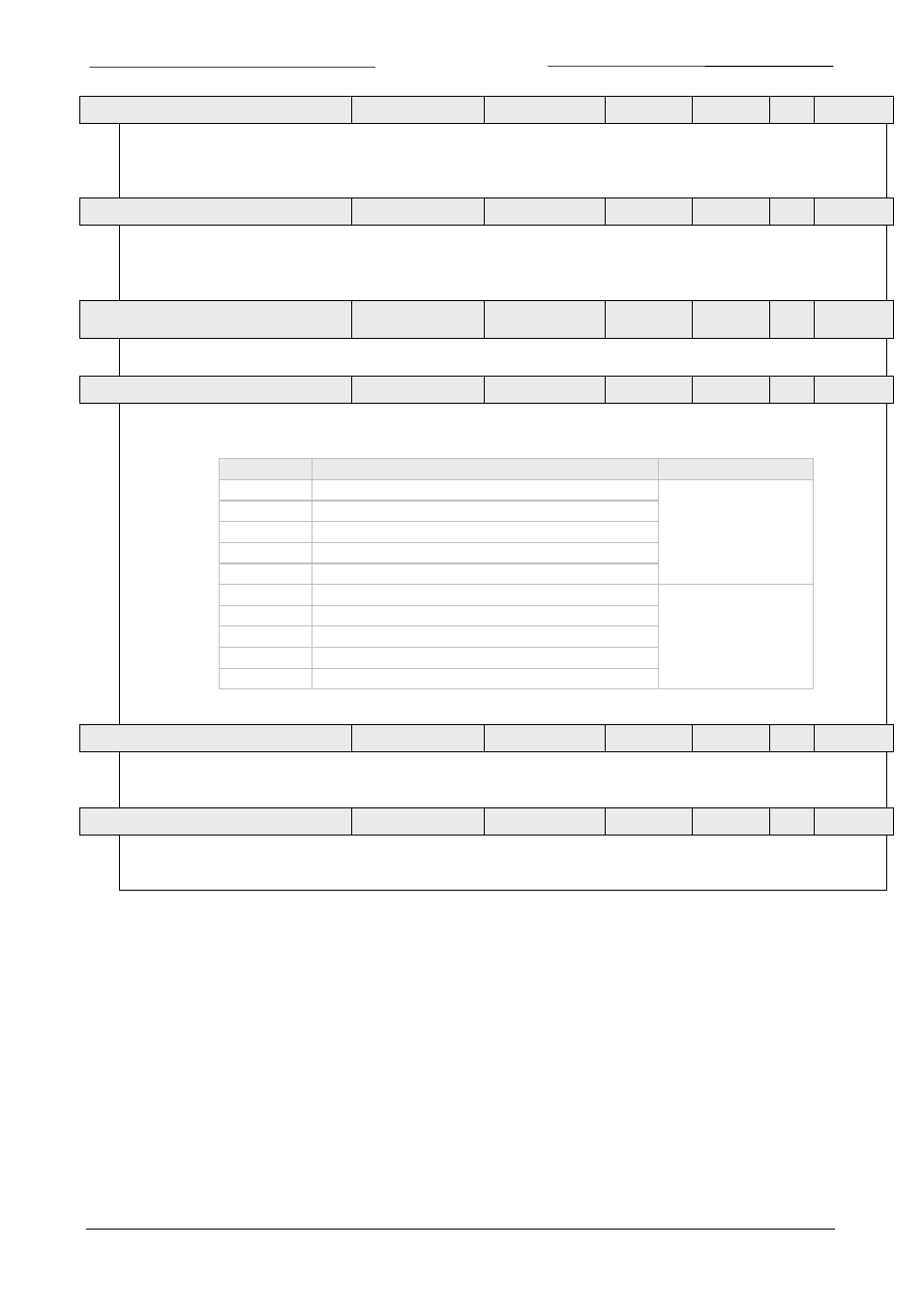
4.17 S
ENSOR TYPE
unsigned char
0…255
RW
Y
22
1/14
Unsigned char used to select proper set of units for certain sensor, together with Counter unit (MBC-II type).
Default setting is 3.
Value
Description
Controller/Sensor
0
pressure (no counting allowed)
Controller
1
liquid volume
2
liquid/gas mass
3
gas volume
4
other sensor type (no counting allowed)
128
pressure (no counting allowed)
Sensor
129
liquid volume
130
liquid/gas mass
131
gas volume
132
other sensor type (no counting allowed)
4.18 C
APACITY
100%
float
1e-10…1e+10
RW
Y
21
13
Capacity is the maximum value (span) at 100% for direct reading in readout units. The readout unit will be determined
by the capacity unit index / string. For each fluid (number) capacity will be stored separately.
4.19 C
APACITY
0%
float
1e-10…1e+10
RW
Y
183
33/22
This is the capacity zero point (offset) for direct reading in readout units. The readout unit will be determined by the
capacity unit index / string. For each fluid (number) capacity will be stored separately.