2 three-phase connection – BECKHOFF AX5000 1,5 A - 40 A User Manual
Page 18
4 Product description
BECKHOFF
Drive Technology
18
Version : 4.6
AX5000
Electrical data
AX5101
AX5103
AX5106
S1 mode (selection)
120 V
230 V
0.3 kVA
0.6 kVA
0.6 kVA
1.2 kVA
1.2 kVA
2.4 kVA
Power dissipation
(2)
35 W
50 W
85 W
Max. continuous braking power
(with internal brake resistor)
50 W
50 W
150 W
Max. braking power
(with internal brake resistor)
14 kW
Min. brake resistor
(
external brake resistor)
47 Ω
Max. braking power
(with
external brake resistor)
15 kW
(1)
I
eff
for max. 7 s
(2)
S1 mode, including power supply unit, without brake chopper
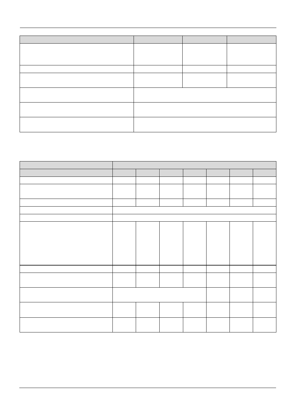
4.4.2.2
Three-phase connection
Electrical data
AX
5101 5103 5106 5112 5118 5125 5140
Rated output current
[A] 1,5
3
6
12
18
25
(1)
40
Minimum channel current
[A]
at full current resolution
0,35
1
1
6
8
12
18
Max. output current
(3)
[A] 4,5
7,5
13
26
36
50
80
(4)
Rated supply voltage
[V
AC
]
3x 100
-10%
– 480
+10%
(2)
Max. DC link voltage
[V
DC
]
890
Rated apparent power
[kVA]
S1-mode (selection)
120 V
230 V
400 V
480 V
0,3
0,6
1,0
1,2
0,6
1,2
2,1
2,5
1,2
2,4
4,2
5,0
2,5
4,8
8,3
10,0
3,4
7,2
12,5
15,0
4,8
10,0
17,3
20,8
8,3
16,0
27,7
33,3
Power dissipation
(5)
[W] 35
50
85
160
255
340
510
Max. continuous braking power [W]
(with internal brake resistor)
50
50
150
90
200
200
150
Max. braking power
[kW]
(with internal brake resistor)
14
26
26
26
Min. brake resistor
[Ω]
(
external brake resistor)
47
47
47
30
22
22
22
(4)
Max. braking power
[kW]
(
external brake resistor)
15
15
15
23,5
32
32
32
(1)
cULus = 24 A
(2)
cULus = AX5118 und AX5125 = 3 x 480 V
AC
± 10%
(3)
I
eff
for max. 7 s
(4)
I
eff
for max. 7 s, if rotating field frequency >3 Hz at max. 40°C
(5)
S1 mode, including power supply unit, without brake chopper
(4)
Brake resistor < 22 Ω –> Please consult our Application Department