BECKHOFF AX5000 1,5 A - 40 A User Manual
Beckhoff, Servo drive ax5000
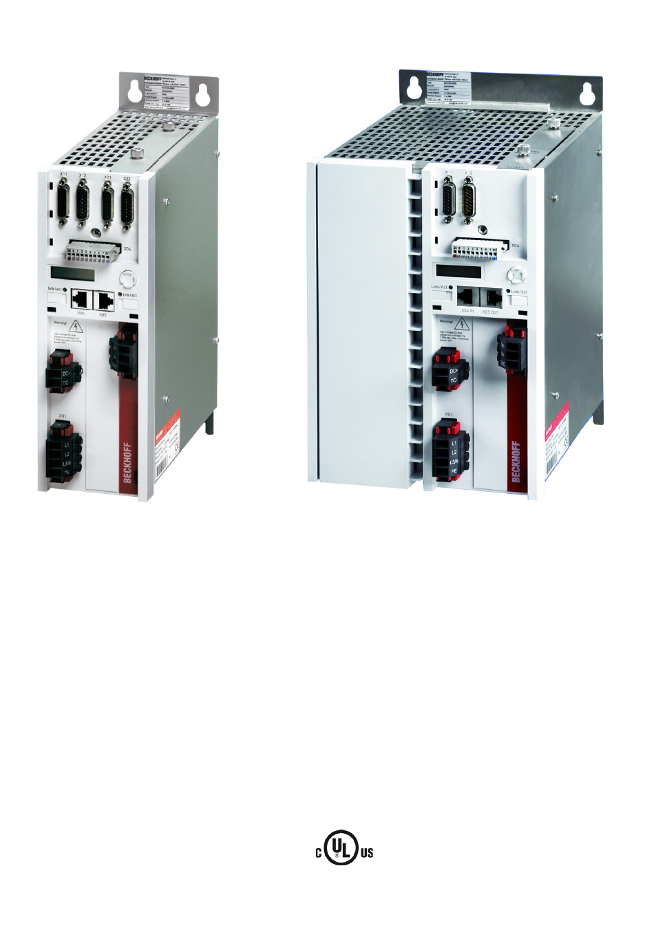
Table of contents
Document Outline
- 1 Foreword
- 2 Safety
- 3 Guidelines and Standards
- 4 Product description
- 4.1 Type code
- 4.2 Scope of supply
- 4.3 Name plate
- 4.4 Technical data
- 4.5 General overview (AX5101 – AX5112 and AX520x)
- 4.6 General overview (AX5118, AX5125 und AX5140)
- 4.7 Overview of connectors/terminal points
- 4.7.1 X01 - wide voltage input
- 4.7.2 X02 - DC link (AX5101 - AX5125 und AX520x)
- 4.7.3 X02 - DC link (Only AX5140)
- 4.7.4 X03 - 24 VDC supply
- 4.7.5 X04, X05 - EtherCAT connection
- 4.7.6 X06 – Digital I/Os
- 4.7.7 X11 (channel A) , X21 (channel B) - feedback, high-resolution
- 4.7.8 X12 (channel A) , X22 (channel B) - resolver/hall
- 4.7.9 X13 (channel A) , X23 (channel B) - motor connection (power)
- 4.7.10 X13 - motor connection (power - only AX5140)
- 4.7.11 X14 (channel A), X24 (channel B)-motor brake, thermal contact, OCT
- 4.7.12 X07 – internal and external brake resistor
- 4.8 Dimensions
- 5 Installation
- 5.1 Mechanical installation
- 5.2 Electrical installation
- 5.3 Motors and cables
- 6 Important information for commissioning
- 7 Project planning – important information
- 8 Appendix