Parallel generator compensation, Parallel control and var/pf control inputs, Voltage matching (optional) – Basler Electric DECS-100 User Manual
Page 40: Power supply inputs, Chassis ground, Power (field) output, Parallel generator compensation -6, Parallel control and var/pf control inputs -6, Voltage matching (optional) -6, Power supply inputs -6
4-6
DECS-100 Installation
9287500991 Rev M
Parallel Generator Compensation
A customer-supplied enable/disable contact for this function connects to the terminals labeled 52L and
52M.
Only dry, ungrounded switching contacts should be applied to the Parallel Generator Compensation
contact input.
Parallel Control and Var/PF Control Inputs
User-supplied contacts at terminals 52L and 52M determine whether AVR or Droop mode is active.
Terminals 52L and 52M typically connect to a 52b auxiliary contact of the generator breaker. User-
supplied contacts at terminals 52J and 52K control whether var or power factor correction is active or
disabled. Terminals 52J and 52K typically connect to the auxiliary contacts of the utility tie breaker. Table
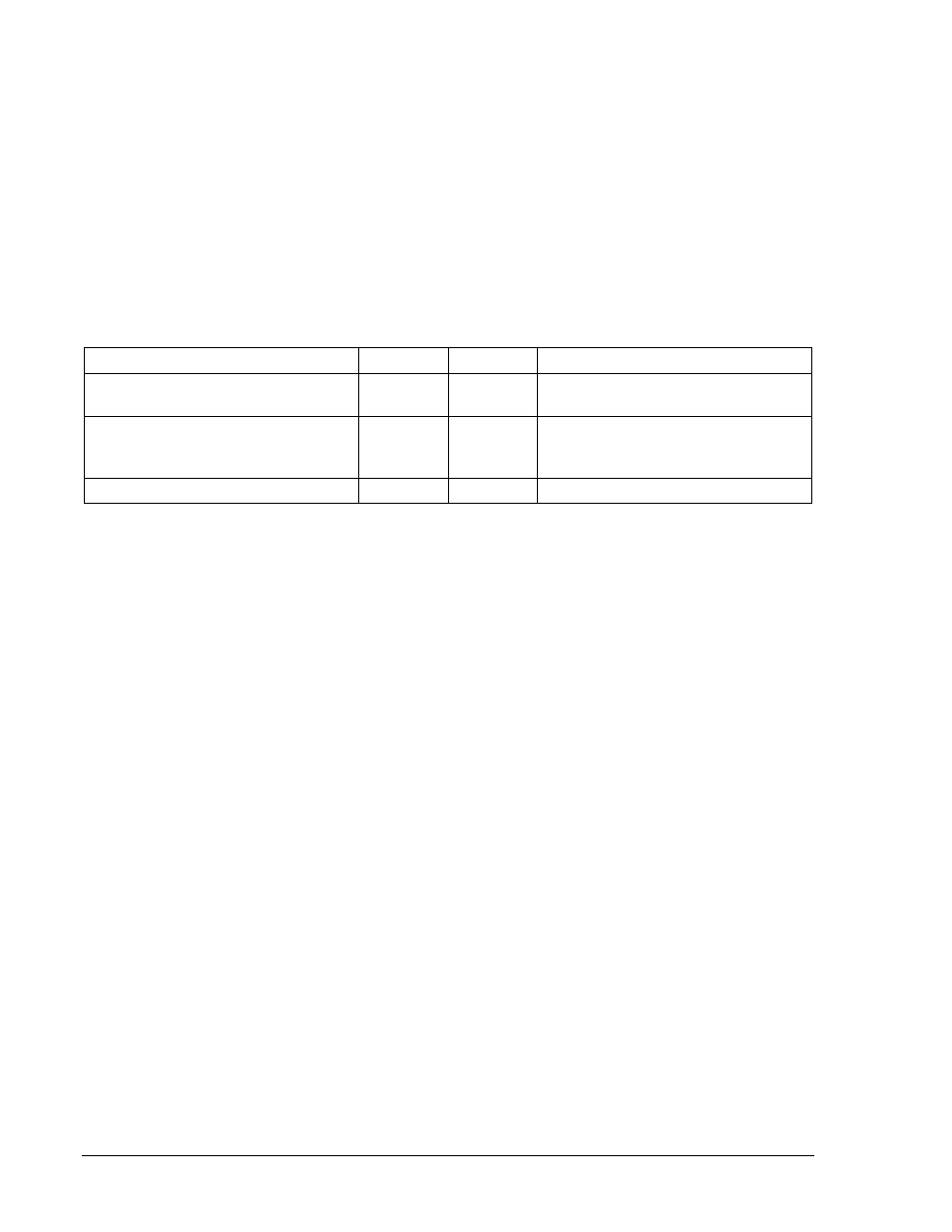
4-3 lists the operating modes achieved for the different 52L/M and 52J/K contact states. A closed state
indicates a continuous contact closure and an open state indicates a continuous open-circuit.
Table 4-3. 52L/M and 52J/K Control Modes
DECS-100 Operating Mode
52L/M
52J/K
Generator Operating Mode
AVR mode active, no droop, optional
var/PF mode disabled
Closed
Closed
Single unit/stand-alone
Droop mode active, optional var/PF
mode disabled
Open
Closed
Paralleled to the utility grid (droop) or
two or more generators islanded
(droop or CCC)
Var/PF mode active
Open
Open
Paralleled to utility grid
Voltage Matching (Optional)
A customer-supplied enable/disable contact for this function connects to the terminals labeled VM and
VMC. Only dry, ungrounded switching contacts should be applied to the Voltage Matching contact input.
Voltage matching is also enabled/disabled by the state of the 52J/K and/or 52L/M contact inputs. In
BESTCOMS™, voltage matching can be configured to be disabled when the 52J/K or 52L/M contact input
is open or just the 52J/K contact input is open.
Power Supply Inputs
Power input terminals are labeled 3, 4, and 5. Single-phase or three-phase power may be applied. Single-
phase power may be applied to any two of the three terminals.
The DECS-100 can be powered directly from a variety of sources as long as the DECS-100 input power
specifications are followed (see Section 1, General Information, Specifications).
Examples of DECS-100 operating power sources are:
• Generator (shunt fed)
• Permanent magnet generator (PMG)
• Auxiliary winding
When powering the DECS-100 from a low-impedance power source, special provisions must be made to
avoid damage to the DECS-100. Examples of a low-impedance power source include a station service
source or power outlet. An Inrush Current Reduction Module, ICRM-7, must be connected between the
power source and DECS-100 input power terminals (see Figure 4-10). The ICRM-7 prevents DECS-100
damage by minimizing the level of inrush current. The ICRM-7 can also be used when programming the
DECS-100. However, the Preliminary Setup paragraphs illustrate an alternate method for temporarily
powering the DECS-100 for programming.
More details about the ICRM-7 are available in Basler Electric publication 9387900990.
Chassis Ground
The chassis ground terminal is labeled GND.
Power (Field) Output
The field output terminals for connection to the generator exciter field are labeled F+ and F–.