Maintenance, Storage, Maintenance -50 – Basler Electric BE1-87T User Manual
Page 92: Storage -50
4-50
BE1-87T Installation
9171300990 Rev V
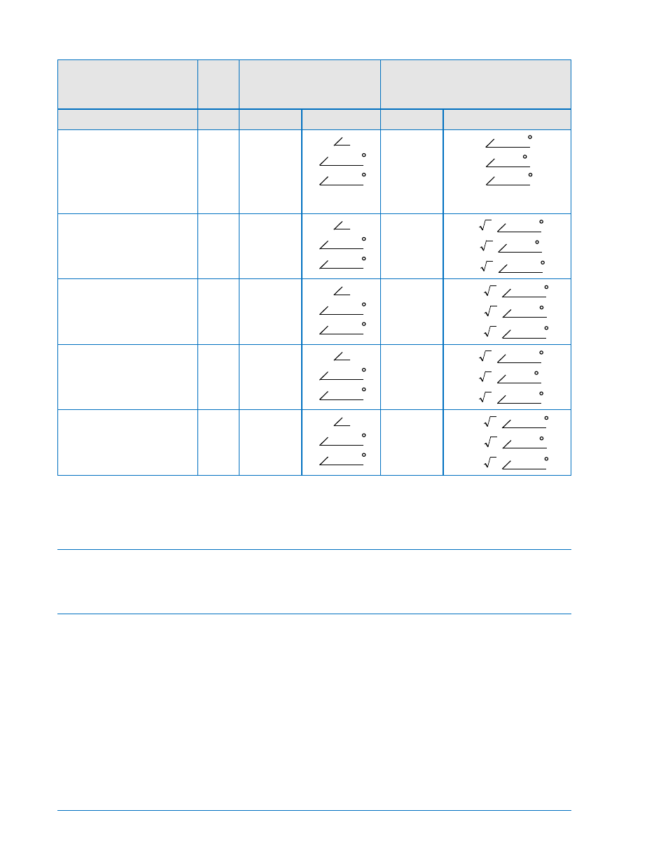
Table 4-4. Input Conditions For Non-Trip Three-Phase Sensing
30° Phase Shift
Compensation Jumper
Settings
Input 1
*
Input 2
*
(Ref. Figure 4-27)
Phase Terminals Phase Angle Terminals
Phase Angle
WYE-WYE,
∆
1-
∆
1, or
∆
2-
∆
2.
(In these cases, input
currents are equal and
180
°
out-of-phase.)
A
B
C
11 & 13
12 & 13
14 & 13
15 & 18
16 & 18
17 & 18
Input 1 is
∆
1, Input 2 is
WYE.
A
B
C
11 & 13
12 & 13
14 & 13
15 & 18
16 & 18
17 & 18
Input 1 is WYE, Input 2 is
∆
1.
A
B
C
11 & 13
12 & 13
14 & 13
15 & 18
16 & 18
17 & 18
Input 1 is
∆
2, Input 2 is
WYE.
A
B
C
11 & 13
12 & 13
14 & 13
15 & 18
16 & 18
17 & 18
Input 1 is WYE, Input 2 is
∆
2.
A
B
C
11 & 13
12 & 13
14 & 13
15 & 18
16 & 18
17 & 18
NOTES:
1. Table 4-4 is for reference only and applies to three-phase units with Input 3 at zero amperes.
2.
*
For A-B-C rotation.
Maintenance
BE1-87T relays require no preventative maintenance other than a periodic operational check. If the relay
fails to function properly, contact Technical Sales Support at Basler Electric to coordinate repairs.
Storage
This device contains long-life electrolytic capacitors. For devices that are not in service (spares in
storage), the life of these capacitors can be maximized by energizing the device for 30 minutes once per
year.
I
θ
I
θ
+ 240
I
θ
+ 120
I
θ
+180
I
θ
+60
I
θ
+ 300
I
θ
I
θ
+ 240
I
θ
+ 120
I 3
( )
θ
+ 150
I 3
( )
θ
+ 30
I 3
( )
θ
+ 270
I
θ
I
θ
+ 240
I
θ
+ 120
÷
I
3
( )
θ
+ 210
÷
I
3
( )
θ
+ 90
÷
I
3
( )
θ
+ 330
I
θ
I
θ
+ 240
I
θ
+ 120
I 3
( )
θ
+ 210
I 3
( )
θ
+ 90
I 3
( )
θ
+ 330
I
θ
I
θ
+ 240
I
θ
+ 120
÷
I
3
( )
θ
+ 150
÷
I
3
( )
θ
+ 30
÷
I
3
( )
θ
+ 270