Saturation factor definitions compared – Basler Electric BE1-87T User Manual
Page 136
A-8
BE1-87T Setting Notes
9171300990 Rev V
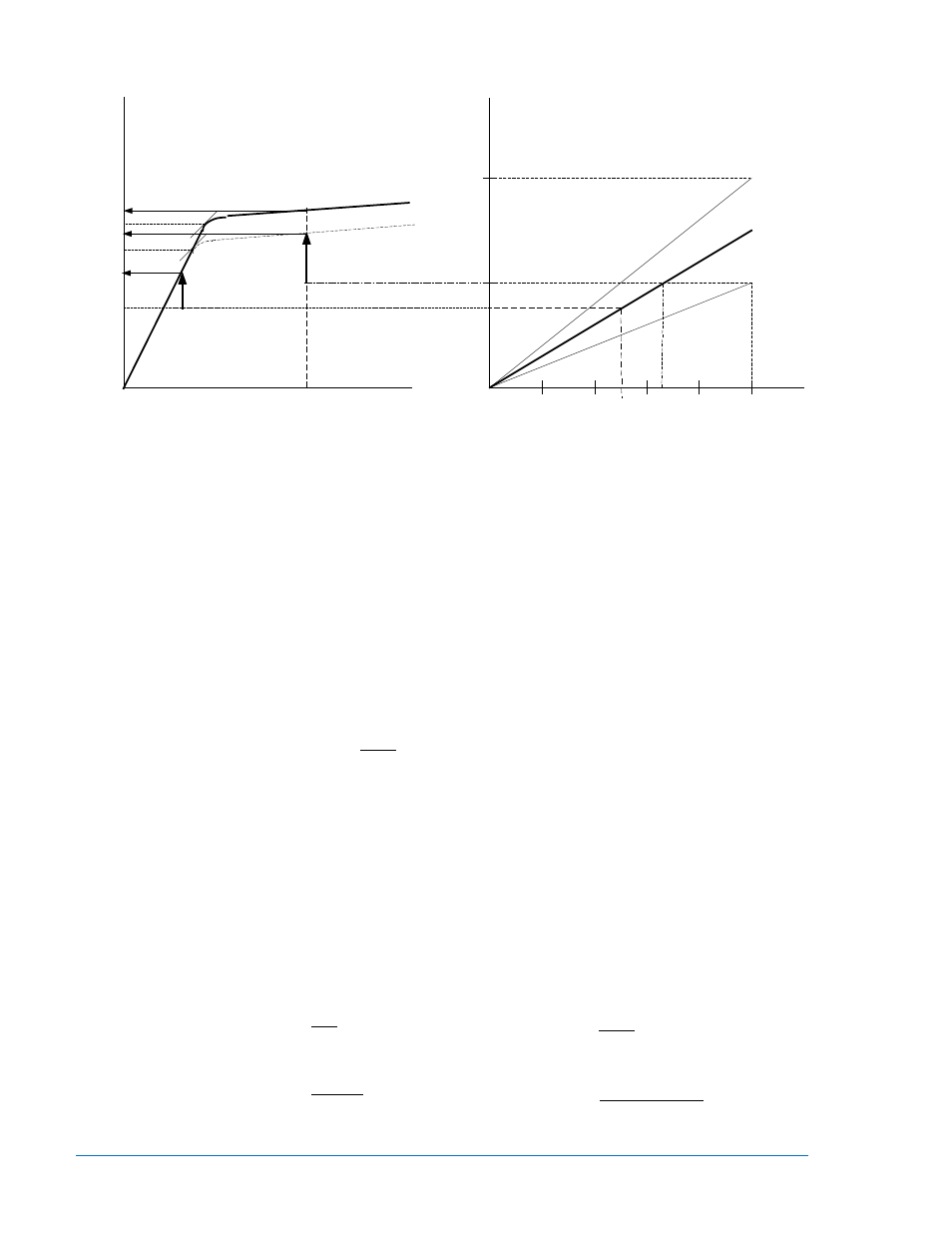
Figure A-8. CT Terminal and Excitation Voltages
This first definition of saturation relates the CT terminal voltage to the accuracy class of the CT (effective
class in the case of multi-ratio CTs). It is practical and easy to calculate since it requires only readily
available data. An application is considered reasonably secure when SF is less than 0.5
Saturation Factor Defined from the CT Excitation Curve
The definition of the saturation factor given above appears to be conservative because it assumes the
worst case ratio error. However, a closer look is required since it neglects the CT internal resistance. It
corresponds to an excitation voltage on a curve passing through point Q in Figure A-8 at which the
excitation current is 10 amperes (the maximum error allowed by the accuracy class definition). The
Rsx100 term represents the voltage drop across the CT internal resistance. A new SF which takes the
internal CT resistance into account can be defined on the excitation curve, as:
Where Ve is the internal excitation voltage (VT+Rs.IF) at the maximum fault current IF and V10` is the
voltage of the curve passing through point Q where the exciting is 10A. This voltage is practically close to
the knee-point voltage VK` which would yield nearly the same (a slightly more conservative) result.
Since in all likelihood, the excitation voltage capability of the CT will be higher ( passing through point R in
Figure A-8 for instance), the saturation factor defined on the excitation curve appears to be lower, i.e. -
more favorable. A detailed analysis can be performed to compare the two saturation factor definitions.
Saturation Factor Definitions Compared
Using the equivalent circuit in Figure A-7 and the ANSI Accuracy Class definition that the CT must be able
to source 20 times nominal current into a standard burden Zc, we now develop a comparative analysis
between the two definitions:
200
400
100
20
40
C200
C400
ZB
IF
IFs
Rs.IF
Rs.100
10A
Ve
Vk
VC
VT
VK`
VT
O
A
C
B
D
P
Q
R
EXC
IT
AT
IO
N
VO
LT
AG
E
EXCITATION CURRENT
RELAY CURRENT
C
T T
ER
M
IN
AL
VO
LT
AG
E
V10
V10`
`
10
`
V
Ve
SF =
VC
VT
SF =
`
10
`
V
Ve
SF =
Zc
IF
ZB
SF
.
100
.
=
)
.(
100
)
.(
`
Rs
Zc
Rs
ZB
IF
SF
+
+
=