See figure 4-34 for 3-phase connections.) – Basler Electric BE1-87T User Manual
Page 77
9171300990 Rev V
BE1-87T Installation
4-35
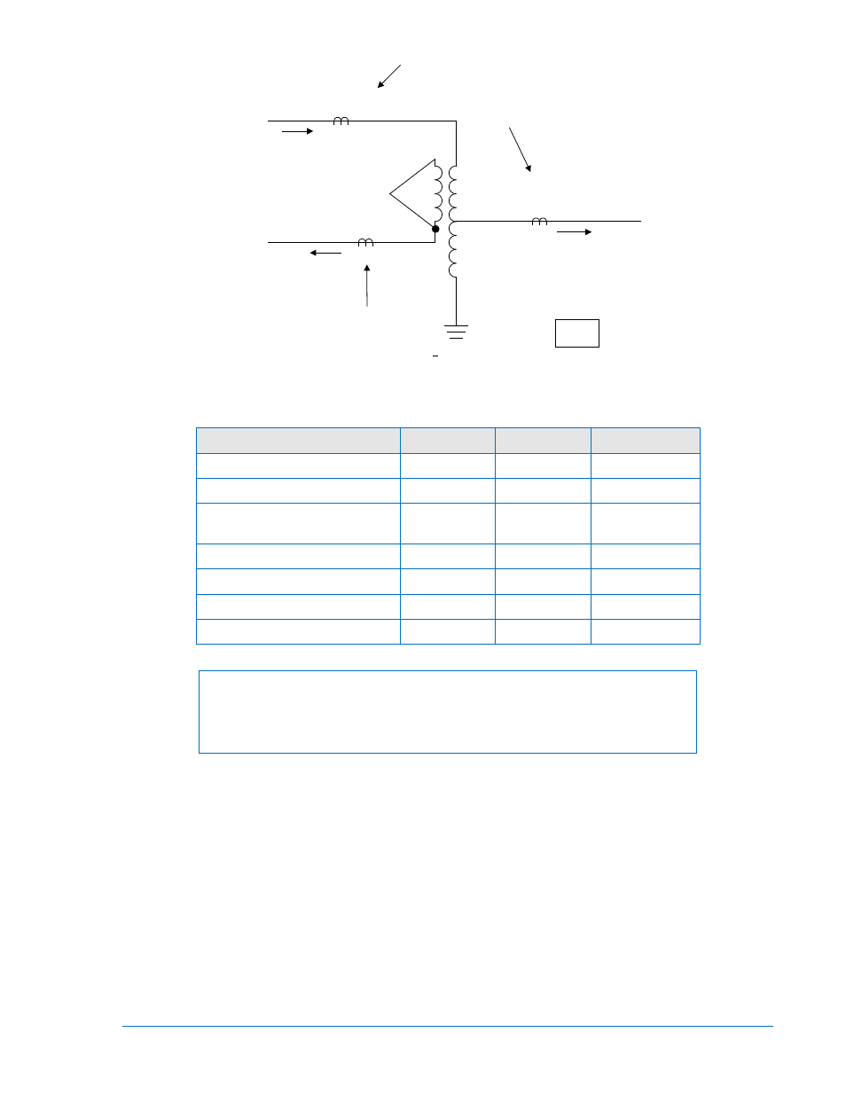
Figure 4-36. Application Example: Autotransformer With Tertiary Winding
(See Figure 4-34 for 3-phase connections.)
Specifications
High side
Tertiary
Low side
kV
345
13.2
138
MVA
200/250
40/50
200/250
CT Ratio
600/5 (MR)
600/5 (T)
3000/5
2000/5 (MR)
1200/5 (T)
CT Accuracy Class
C400
C800
C400
CT Resistance (ohms)
0.3
1.5
0.6
One-Way Lead Burden (ohms) 0.7
0.7
0.7
CT Connection (Three-Phase) WYE
WYE
WYE
NOTE
Three-phase is the most common application of the BE1-87T. Using single-
phase relays requires a Delta connection for the High side and Low side CTs
(IA-IB to match the tertiary connection in the example detailed in Figure 4-34).
Step 3. Three-Phase Units Only: Adjust the phase compensation jumpers on Analog Board #2, shown
in Figure 2-4 and Figure 4-27, (or use the procedure listed in Testing Three-Phase Units without
Changing Jumpers, in Section 5).
Because of the grounded winding in this example, as shown in Figure 4-35 and 4-34, the high-
side, and low-side zero-sequence currents must be canceled.
∆
2 position is selected to align
the High side and Low side secondary current phasors with the tertiary phasors which lead by
30° in this example:
HIGH
TERTIARY
LOW
Jumper
Position:
∆
2
WYE
∆
2
Step 4. Determine the relay current (I
R
):
X
X
600/5MR
600/5T
3360 A (3 ∅)
3375 A (1 ∅)
13,280 A (3 ∅)
3000/5
2000/5MR
1200/5T
138 kV
8400 A (3 ∅)
9000 A (1 ∅)
345 kV
02-12-98
D240-004
BE1-87T
WYE (3)
WYE (3)
(12)
(12)
13.2
kV
WYE (3)
A
1
(12)
+
10% LTC (11)
HIGH
SIDE
TERTIARY
LOW SIDE
I
I
R
S
=
× Conversion Factor