6 8 optional equipment, For qualified installers only), Optional wall-mounted rheostat – Avalon Firestyles 564 SS Gas Installation User Manual
Page 68
6 8
Optional Equipment
(for qualified installers only)
Travis Industries
4 0 7 0 6 2 0
100-01188_000
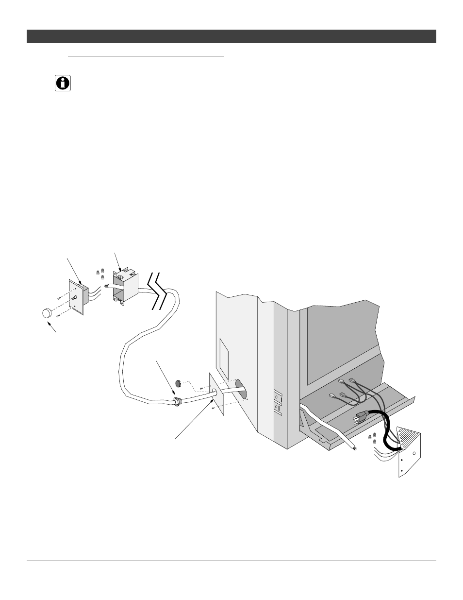
Optional Wall-Mounted Rheostat
NOTE: Many areas require all wiring to be installed by a qualified electrician. Check with your local
building official for any requirements in your area.
1
Remove the rheostat from the rheostat assembly.
2
Detach the three wires leading from the rheostat (secured with wire nuts). Attach the rheostat
assembly to the fireplace (see the illustration on the previous page). Attach the quick connects from
the rheostat to the quick connects from the accent light assemblies (see the illustration on the
previous page).
3
Attach three suitable wires (insulated & sheathed) to the rheostat. Install the rheostat into a junction
box at the remote location. Run the wire from the junction box to the fireplace. Use the included wire
clamp to secure the wiring as it passes through the fireplace (see the illustration below).
4
Connect the three wires from the rheostat to the three wires on the wiring harness disconnected in
step 2 (use the included wire nuts). Plug the rheostat assembly into the receptacle inside the
fireplace.
A 7/8” diameter hole is provided on this cover
plate (both sides). If this hole is already used
for a gas inlet, you can drill an additional 7/8”
hole in this cover plate.
Wire Clamp (included)
Junction Box
Rheostat
(removed from
rheostat assembly)
Knob (included)
Rheostat
Assembly