6 0 optional equipment, Blower, For qualified installers only) – Avalon Firestyles 564 SS Gas Installation User Manual
Page 60: Wiring diagram - blower wiring harness, Blower installation
6 0
Optional Equipment
(for qualified installers only)
Travis Industries
4 0 7 0 6 2 0
100-01188_000
Blower
(part # 99000156)
Make sure power to the fireplace has been turned off prior to installation (disable the service breaker).
Do not connect 110-120 VAC to the gas control valve or wiring system of this fireplace.
It is easier to install the blower prior to connecting the gas line.
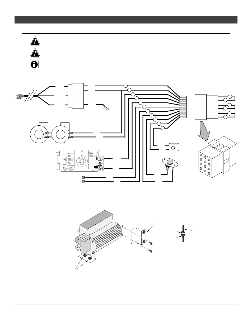
Wiring Diagram - Blower Wiring Harness
7
4
10
9
1
3
Optional Blowers
Green
Hot
(black)
Common
(white)
Ground
(green)
Blower
Snap Disk
Power In
Molex
Connector
Power Supply
Ground
(attached to stove)
White
Black
1
3
5
7
2
4
6
8
9
12
11
10
3
6
White
9
2
5
Black
Remote
Control
Molex
Connector
8
11
Blue
Blue
Optional Regulator
Solenoid
1
4
Black
Black
7
Black
Black
10
Red
Brown
Rheostat
Gas Control
Valve
Blower Installation
1.
Attach the right side blower to a blower bracket following the directions below (note: newer blower kits
are pre-assembled). Repeat for the left side blower.
Make sure these two
grommets are in place
(they insulate the fireplace
from blower vibration)
Side View
Grommet
Blower
Bracket
Bushing
Install the brackets to the blower with
two #8 x 3/8” (shorter, silver) screws.
Make sure these two grommets
and bushings are in place.